Download
1 / 29
300 likes | 347 Views
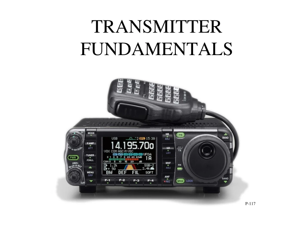
TRANSMITTER FUNDAMENTALS. P-117. Audio Frequency Definition. Acoustic, mechanical, or electrical frequencies corresponding to normally audible sound waves which are of the frequencies of approximately 13 to 13,000 hertz. Radio Frequencies. The Electromagnetic Spectrum. Oscillators.

E N D
TRANSMITTER FUNDAMENTALS P-117
Audio Frequency Definition Acoustic, mechanical, or electrical frequencies corresponding to normally audible sound waves which are of the frequencies of approximately 13 to 13,000 hertz
Oscillators • The oscillator is the heart of a transmitter. • It creates the frequency that the transmitter emits. • Oscillators can be fixed, (crystal controlled) or they can be variable, such as a variable frequency oscillator (VFO)
CW Transmitter Page 131
Example of Chirp • Chirp is caused by an unstable oscillator • The frequency changes slightly every time the key is pressed. As a point of interest, the letter C is added to the RST report to let the sending station know that they have chirp on their signal. EG “UR RST IS 559C 559C”
AMPLITUDE MODULATION • Amplitude modulation changes the amplitude (strength) of the transmitted signal. • A modulator stage is added to a transmitter that uses the signal from the microphone to change the transmitted signal in a corresponding manner. (It impresses the audio frequency on top of the radio frequency). • The stronger the audio signal, the more the amplitude of the carrier change. • When no audio is applied, the transmitter produces an unmodulated carrier like a CW transmitter.
FM Fundamentals • Frequency Modulation changes the frequency of the oscillator. The amplitude always remains the same. • Like an AM transmitter, a modulator stage is used, but with an FM transmitter, it is connected to the oscillator. • FM is best for local communications because the audio is ‘hi fi’ and can be clearly understood when the signal is weak. Because of this it is mostly used for line of sight VHF and UHF work.
Single Sideband Fundamentals • SSB was developed as a more efficient method of transmitting audio frequencies. • Unlike AM modulation, there is no carrier signal. All of the energy goes toward transmitting audio frequencies. • An SSB uses less bandwidth than an AM signal. (3 khz vs 6 khz) • SSB has become the de facto standard for HF Amateur communications.
SSB Operating Notes - 1 • Like AM and FM, SSB signals can be overmodulated. • The result is distortion and splatter. • SSB Transmitters have a built in control to automatically adjust the speech level. (Called the automatic level control ALC) • The ALC can’t handle audio signals that are excessively strong. • SSB transmitters have a meter that shows how the ALC is working. If the ALC is ‘going into the red’, then the operator has to talk softer, or turn down the microphone gain.
SSB Operating Notes - 2 • Since there is no carrier, the power in an SSB signal. It is measured using Peak Envelope Power (PEP) • PEP is the maximum power in the signal peaks.
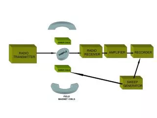
Receiver Characteristics Selectivity Sensitivity Stability Image Rejection
Selectivity - Is a measure of a receiver’s ability to separate received signals.
Sensitivity Is a measure of a receiver’s ability to detect weak signals. Known as the signal to noise ratio measured in Decibels. (There are two types of noise.. Internal and External) The formula for determining the performance is: SIGNAL + NOISE NOISE
Stability Stability is the resistance to frequency drift caused by temperature, voltage variations and proximity to the body. Modern receivers are usually measured in parts per million. EG 0.5 PPM Older non digital receivers used crystal calibrators to make sure they were on frequency.
Cross Modulation Caused by extremely strong signals overloading the RF stage. Can cause minor to severe distortion. Modern communication receivers have an attenuator to lower the gain of the RF amplifier
Bandwidth Describes how wide the filter is in the front end of the radio. The bandwidth must match the bandwidth of the desired signal. - CW could be 500 Hz - RTTY with a shift of 170 Hz would need 250 Hz - SSB is typically around 2.4 Khz - Amateur FM is typically 10 Khz (+/- 5 Khz)