Download

1 / 43
640 likes | 1.17k Views
Finite Element Analysis of Electric Machines ------The Solver and Its Application Danhong Zhong Department of Electrical Engineering The Pennsylvania State University. Outline. Motivation S teady-state finite element solver Low rotor loss permanent magnet machine design

E N D
Finite Element Analysis of Electric Machines ------The Solver and Its Application Danhong Zhong Department of Electrical Engineering The Pennsylvania State University
Outline • Motivation • Steady-state finite element solver • Low rotor loss permanent magnet machine design • Summary and future work
Electric Machines in New Technologies Flywheel for frequency regulation for renewable and distributed generation (Credit: Beacon Power)
How do we design a machine that suits our need?
Flywheel energy storage system Motor/Generator test setup for flywheel system
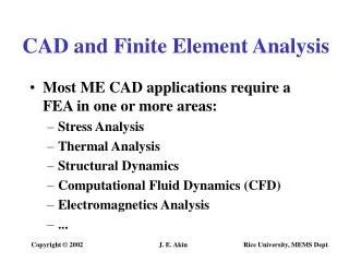
Design Methods • Rules-of-thumb, empirical tables, design equations, a designer’s intuition are all valuable • Classic Way----prototyping • Large-scale numerical simulation
Synchronous Permanent Magnet (PM) Machines • Magnetic excitation is supplied by high-energy permanent magnet • No power loss is associated • with machine field excitation • High power/weight ratio • ----Popular choice for • high-speed motor/generator • applications
Rotor losses • Rotor exposed to high electrical frequency harmonics • Heat generated • Rotor spins in vacuum, supported by magnetic bearings • Only method of heat transfer is through blackbody radiation, which is a relatively poor heat transfer mechanism
Temperature dependence of Neodymium Iron Boron • The properties of many materials in the flywheel rotor will degrade with increasing temperature • E.g., the intrinsic coercivity of Neodymium-Iron-Boron decreases significantly with temperature, creating a risk of demagnetization • It is therefore important to minimize rotor losses in this application Change of intrinsic coercivity of Neodymium Iron Boron with respect to temperature (courtesy Dexter Magnetics)
Solver overview • Programmed in MATLAB environment • 2-D finite element analysis • Software capable of: model building mesh generation steady-state solution solving (time stepping) rotor losses calculation • Uses GMRES method to speed up steady-state solution • Allows study of rotor losses when insulating barriers exist in the 2-D plane of the rotor (e.g., segmenting permanent magnets)
Road Map • Maxwell’s equation --The governing Partial Differential Equation(PDE) of the problem • PDE -Finite Element Equations • Main techniques used in achieving the steady state solution.
(1) Mathematical model Maxwell’s equations: Constitutive Laws: Governing Partial Differential Equation (PDE)
Finite Element Method • The object isdivided into Finite Element mesh • A simple relationship is used to represent the variables anywhere in the element by variables on the nodes of the element. • Within the element, approximate functions in terms of nodal values are then derived from the PDE Mesh (16761 points 33232 elements)
(1) The method of weighted residuals Define a residual function: (2) The solution of the PDE should satisfy that, for a given weight function w, element (3)
(5) Finite Element Formulation The finite element formulation is given as: (4) Where D, K :global matrix decided by material properties and element shape M, M : represents magnetization in ferromagnetic materials or permanent magnets, can be a nonlinear function of x I s : forced current flowing in stator windings
If we define the nonlinear state transition function as , this becomes: (6) Steady-State Analysis Under steady-state assumptions, after one period T we wish to achieve the same primary variables, i.e.
Steady-State Solution Techniques (5) (6) • The state transition function in (6) is determined by (5) • To achieve the steady-state solutions, we used the following numerical techniques: • Backward Euler Integration • Shooting-Newton Algorithm • Matrix-free GMRES
In our solver we define Time integration of the differential equation Initial Value Final Value Modify NO Calculate Modification Error < Tolerance? YES End Iteration Target Value (=Initial Value) Shooting Newton Method The steady-state solution in the time domain is obtained by using a “shooting” Newton method: (7) Applying the Newton-Raphson method, we get: (8) Where Jis the Jacobian of the nonlinear state transition function
Matrix-free GMRES Method can not be explicitly written The Jacobin • Generalized minimum residual method (GMRES) : • A Krylov-subspace method • When solving Ax=b, no direct access of matrix A is used, A only need to be accessible via a subroutine that returns y=Az (8) x b A
Efficiency Improvement By using GMRES, the computation time of the shooting-Newton method is dramatically reduced.
Harmonic analysis After we achieve the steady-state solution, we perform a Discrete Fourier Transform of x(t) and calculate the eddy current rotor losses for each harmonic.
Rotor Loss Design Study • Design parameters are changed to study the effect on rotor losses • The stator current peak is adjusted to maintain constant steady-state mechanical power
Other Rotor Design Aspect • Laminated backiron • Different permanent magnet materials
Stator Design: “Open” Slot vs. “Closed ” Slot “open” slot “closed” slot
Techniques for Reducing Rotor Losses • Laminating rotor backiron • Segmenting the Permanent magnet poles • Increasing slot number • Closing the stator slots
Summary • Purpose of Finite element analysis for electric machines • The flywheel energy storage system • The steady-state nonlinear finite element solver • Its application
Future Work • Further research into numerical modeling of electric machines • Special machine design and analysis 2011 Chevrolet Volt Propulsion System (Credit: GM)
Thank you! This work has been supported by NASA Grant NAG3-2598
Permanent Magnets Currents flowing in permanent magnet are eddy currents. In machine design, magnets can be electrically insulated from each other and the rotor backiron. Eddy currents meet large impedance at the end of the machine, surface charge will accumulate and electric potential is built across the magnet
Electric Scalar Potential Dynamics (2) The charge relaxation time constant / is extremely small in permanent magnets, and so our system consists of a set of “fast” dynamics (electric scalar potential) and “slow” dynamics (magnetic vector potential). Therefore, singular perturbation techniques can be used to analyze the system.
Singular Perturbation Analysis Techniques • Under singular perturbation theory, when analyzing the “fast” dynamics, the “slow” variables can be assumed to be essentially constant • If the fast dynamics are stable under this condition, the “fast” variables will converge to a quasi-steady-state value, which is a function of the “slow variables” • When analyzing the “slow” dynamics, it can be assumed that the “fast” variables have converged to their quasi-steady-state value discussed above. small (3)
Applying Finite Element Method To solve the Partial Differential Equations use 2D finite element method Primary variable : A and Element type : triangular Shape functions : linear Procedure used : weighted residuals Error distribution principle : Galerkin’smethod Boundary conditions:
For a nonlinear equation, the Newton-Raphson Method provides the following iterative procedure to solver for x: Define : and it’s called the Jacobian of In our solver we define Newton-Raphson Method Applying the Newton-Raphson method, we get: (5) Where Jis the Jacobian of the nonlinear state transition function
In (5), is not known explicitly but is determined through Backward Euler Integration. Thus: Equation solving Now we look closely at the steady state iterative equation : (5) can not be explicitly written either and would have to be calculated using a form of numerical integration
One way of solving for the Jacobian is to differentiate both sides of (4) with respect to Where and are matrices derived from (4). can then be computed by repeatedly solving (6) starting from the initial condition Matrix-Matrix multiplication on the right side and LU-factorization on the left side. If the vector has components, the computation work per time step is of at least order Equation solving (2) Computation load analysis of this method:
Backward Euler Integration Consider the problem: The Backward Euler Integration Method calculate y at step n+1 implicitly by : In the solver we separate the period T into a number of time steps h. Provided a solution at time t1, x(t1), we then can compute the solution x(t1+h) at time t1+h, by applying the backward Euler integration to (5) over the time interval h: (5) (7)
Now we consider solving the problem using GMRES method. By using GMRES method, we don’t need to provide explicitly. Instead, we only need to provide . We apply the procedure (6) to a vector Application of the GMRES Computation load analysis of this method: Matrix-vector multiplication on the right side and LU-factorization on the left side. Typically the number of iterations required by GMRES to achieve a sufficiently low relative error is substantially smaller than problem size. So by using GMRES, the numerical efficiency is improved.
Post-processing: rotor loss calculation The eddy currents in rotor are : After we achieve the steady-state solution at time 0, the entire response x(t) can be calculated by integrating (5) for one period. We perform a Discrete Fourier Transform of x(t) and calculate the eddy current rotor losses for each harmonic in each element.