Download
1 / 37
370 likes | 601 Views
The MAGIC Telescope. EPS (July 17 th -23 rd 2003) Aachen, Germany. Razmick Mirzoyan Max-Planck-Institute for Physics Munich, Germany. Outline. The MAGIC Collaboration Aiming for low threshold Physiscs goals The Telescope Design overview MAGIC Key elements for low threshold

E N D
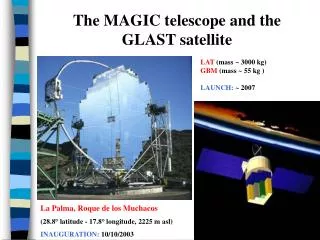
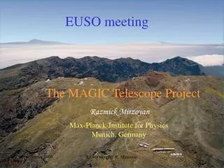
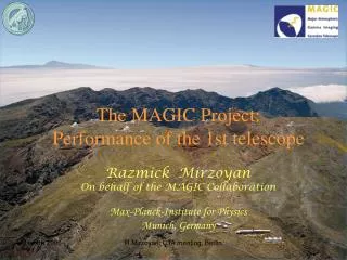
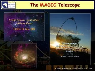
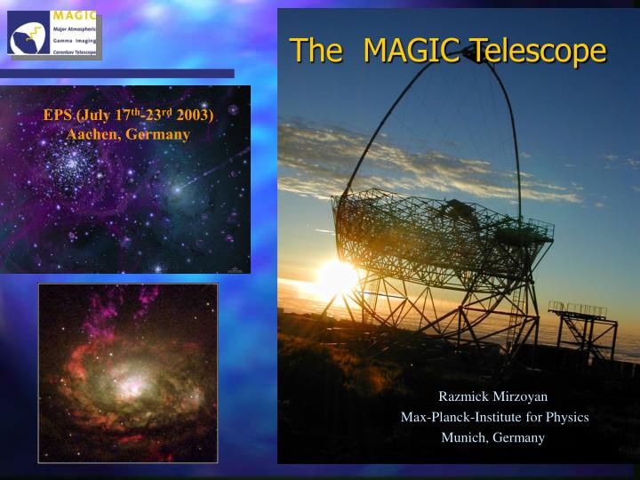
The MAGIC Telescope EPS (July 17th-23rd 2003) Aachen, Germany Razmick Mirzoyan Max-Planck-Institute for Physics Munich, Germany
Outline • The MAGIC Collaboration • Aiming for low threshold • Physiscs goals • The Telescope • Design overview • MAGIC Key elements for low threshold • Status of commissioning of the telescope elements • Plans & Conclusions
The MAGIC project • First presentation in 95 at the ICRC, Rome, (Bradbury et al) • Approval of funding only late 2000 • Start of construction in 2001 • Now commissioning • Innauguration October 10th
The MAGIC Collaboration Major Atmospheric Gamma-Ray Imaging Cherenkov Telescope Barcelona IFAE, Barcelona UAB, Crimean Observatory, U.C. Davis, U. Lodz, UCM Madrid, INR Moscow, MPI Munich, INFN/ U. Padua, INFN/ U. Siena U. Siegen, Tuorla Observatory, Yerevan Phys. Institute, INFN/U. Udine , U. Wuerzburg, ETH Zurich • MAGIC is an international collaboration building a17 m Cherenkov Telescopefor the observation ofHE cosmic –rays. • Main aim: to detect –ray sources in the unexplored energy range: 30 (10)-> 250 GeV • MAGIC was a challenging design to decrease theenergy threshold, by pushing the technology in terms of mirror size,trigger, camera sensors and electronics. • MAGIC shall provide the lowest threshold ever obtained with a Cherenkov telescope!!!
The unexplored spectrum gap • Satellites give a nice crowded picture of energies up to 10 GeV. Effective area << 1 m2 • Ground-based experiments show very few sources with energies > ~300 GeV. Effective area > 104 m2
The MAGIC PHYSICS Goals • Cosmological g ray horizon • AGNs • Pulsars • GRBs • Tests on Quantum Gravity effects • SNRs • Cold Dark Matter
Absorption of extragalactic - rays Any that crosses cosmological distances through the universe interacts with the EBL Attenuated flux function of g-energy and redshift z. For the energy range of IACTs (10 GeV-10 TeV), the interaction takes place with the infrared (0.01 eV-3 eV, 100 m-0.4 m). Star formation, Radiation of stars, Absorption and reemission by ISM EBL By measuring the cutoffs in the spectra of AGNs, MAGIC can help in determining the IR background MAGIC
MAGIC phase I MAGIC phase II Optical Depth & GRH Optical Depth The probability of being absorbed for HE gamma crossing the universe is the integration of the cross-section over the incident angle and along the path from its origin to the observation. Gamma Ray Horizon (GRH) This produces a reduction factor e- in the ray flux. The GRH is defined as the “z” for the observed energy “E” that fulfils: i.e. a reduction 1/e of the flux of the extragalactic source.
EBL absorption The absorption effect seen at TeV energies on a nearby blazars H1426+428 (z=0.129) Mkn 501 (z=0.034)
MAGIC Expected sources MAGIC is not operating yet, so it is still a mystery how many extragalactic sources is going to detect but one can use the EGRET catalogue to find some very provable candidates. Assuming the foreseen MAGIC characteristics and 50 hours of observation time for each of these candidates, we expect to be able to measure the GRH at different redshifts.
Measurements from 20 expected sources From the extrapolation of the EGRET catalogue datawe expect to be able to measure the GRH for 20 extragalactic sources using 50 hours for each. The Energy cut-off could be due to the source itself. It could be unfolded if one gets several sources at the same redshift. So we selected among these 20 sources the ones that have several at the same redshift and we kept 7. We can use half of the sample to improve EBL knowledge; i.e. to reduce systematics
4-fold nn-logic Pulsars • Where do g-rays come from? Outer gap or polar cap? • Many of the ~170 EGRET unidentified sources may be pulsars. • 7-ray pulsars seen by EGRET. Only upper limits from present IACTs (spectral cut-off)
Gamma Ray Bursts • Mechanism not yet fully resolved. • MAGIC take advantage: • Huge collection area • Fast repositioning. • Low energy threshold Under the assumption that it is possible to extrapolate the GRB energy spectrum in the GeV region, MAGIC can observe 2-3 GRB/year MAGIC is designed to observe the prompt emission of a GRB!
Other Physics targets for MAGIC • Search for neutralino annihilation gamma-ray line (galactic center, neighboring galaxies, globular clusters) • Tests of possible Lorentz invariance deformation: search for delay of HE gamma rays in rapidly varying phenomena at large distances (AGN flares, GRBs)
Key elements of the MAGIC telescope • 577 pixels enhanced QE, 3.9 deg FOV camera + advanced calibration system • 17 m diameter reflecting surface (240 m2 ) • Light weight carbon fiber frame • Active mirror control • Analog optical signal transport • 2-level advanced trigger system
The frame • The 17m diameter f/1 telescope frame is a lightweight carbon fiber structure (tube and knot system) • The foundation started in September 2001 and the telescope was completed in Dec. 2001. The assembly of the frame took only one month
The reflector • The overall reflector shape is parabolic (f/1), isochronous, to maintain the time structure of Cherenkov light flashes in the camera plane • Better light of night sky rejection (less pile-up) • Tessellated surface: • ~950 mirror elements • 49.5 x 49.5 cm2 (~240 m2) • All-aluminium, quartz coated, diamond milled, internal heating • >85% reflectivity in 300-650nm
mirror assembly Adjustment legs screwed on the mirror Cabling of the mirror internal heating 2 mirrors mounted on a panel
Optical alignment Final spot of a panel after The precise alignment of the mirrors 4 mirrors spots after the pre-alignment close to the virtual center of the MAGIC camera
The Active Mirror Control • The panels can be oriented during the telescope operation through an Active Mirror Control system (AMC) to correct for possible deformation of the telescope structure
The alignment of the mirrors • The alignment of the first 103 mirrors in the telescope structure has been done by using a 20 W light source at a distance of 920m • The camera plane was moved 29 cm backward to focus the lamp light ~1 pixel 103 spots before and after the alignment
Two sections: Inner part: 0.100 PMTs Outer part: 0.200 PMTs The camera • includes 577 PMTs Plate of Winston cones Active camera area 98 %
The camera Pixels: • The photocatode QE is enhanced up to 30 % and extended to UV by a special coating of PM surface with milky wavelength shifter • Each PM is connected to an ultrafast low-noise transimpedance preamp. • 6-dynode HV system zener stabilized with an active load 240 m2 -> 312 m2 !!!
The camera status • The temperature inside is controlled by a water cooling system with temperature/humidity sensors. • The camera was completed in summer 2002, after extensive tests and characterization • installed in November 2002 • commissioned March 2003 after the winter break. • First starlight using DC current readout was recorded on March 8th.
The readout Cherenkov light pulses from air showers are typically ~ a few ns long • Pixel signals transported 162 m over optical fibres: • No signal dispersion • Cable weight, optically decoupled, noise inmune. • Sampling using 300 MHz-1GHz FlashADCs: • g/h discrimination through signal shape • Noise reduction • Event buffering, telescope system synchronization...
Discriminators L0 Set the minimum number of photoelectrons per pixel to be used in the trigger Make a tight time coincidence on simple pattern of compact images and enable L2 Level 1 L1 • Perform an advanced pattern recognition • to use topological constraint: • pixel counting in a given region of the detector • mask hot spots like bright stars • rough image reconstruction, etc…. • On-line event selection Level 2 L2 To FADC Trigger Two level trigger system The level 1 (L1) is a fast coincidence device (2-5 ns) with simple patterns (N-next-neighbour logic) on single trigger cells. Level 2 (L2) is slower (50-150 ns), and can perform a global sophisticated pattern recognition
On-line image analysis on the trigger event Off-line analysis Trigger • - 44 GeV L2 pattern recognition Trigger display On-line Off-line
Trigger status L1T L2T The trigger has been commissioned since: Dec. 2002 (LT1) March 2003 (LT2)
IPE IPE IPE IPE IPE IPE NET NET CE CE The Data Acquisition System • Needs: • 577 PMT x 1 Byte x 30 samples x 1 kHz ~ 20 MByte/s(x 11 hours ) ~ 800 GB/night (longest nights in December) • Cheap PC based solution: • Multiprocessor threaded system. • PCI FPGA based readout card & RAID0 disks system.
GRB alert: early follow-up • The light weight structure and the low inertia of the structure allows a fast slewing time in such a way that the telescope will be able to perform an early follow-up of a Gamma Ray Burst • With the engines at 70% of full power, the telescope was able to move of 180º in both axes in less than 30s
Future Plans • August-September -> finishing installation of mirrors and electronics • September -> move to new counting house • October 10th Inaguration • Winter 2003-2004: start regular observation
Conclusions • So far all the new technical and technological novelties implemented in MAGIC behave as expected • In the next few month we will make extensive tests of the apparatus with engineering and physics runs • We are considering MAGIC as the first element of an international observatory to study the deep universe with high energy gamma rays. • Our proposal is to transform the MAGIC site, Roque de los Muchachos, in the “European Cherenkov Observatory” ECO