Download
1 / 36
360 likes | 541 Views
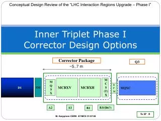
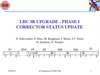
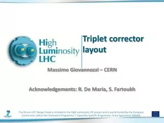
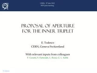
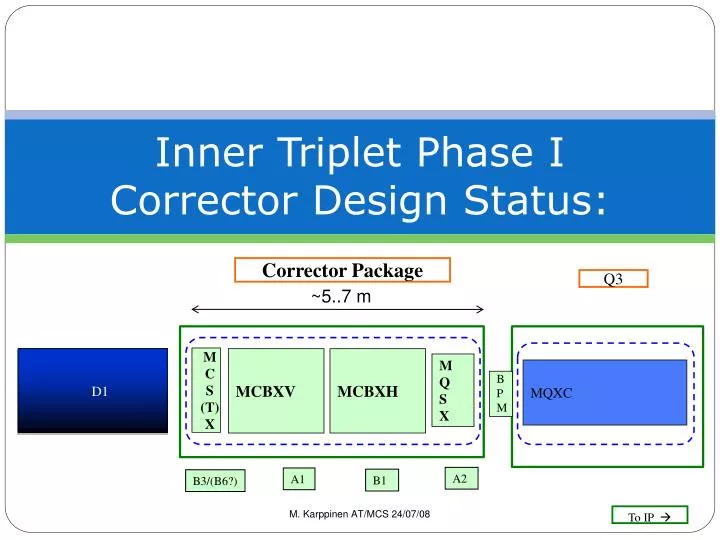
Inner Triplet Phase I Corrector Design Status:. Corrector Package. Q3. ~5..7 m. M C S (T) X. D1. MCBXV. MCBXH. M Q S X. MQXC. B PM. A2. A1. B1. B3/(B6?). M. Karppinen AT/MCS 24/07/08. To IP . Outline. Corrector requirements and constraints

E N D
Inner Triplet Phase I Corrector Design Status: Corrector Package Q3 ~5..7 m M C S (T) X D1 MCBXV MCBXH M Q S X MQXC B PM A2 A1 B1 B3/(B6?) M. Karppinen AT/MCS 24/07/08 To IP
Outline • Corrector requirements and constraints • Some corrector specific fabrication aspects • Design status: • MCBX (CERN) • MQSX (STFC/RAL & CERN) • MCSX (CIEMAT & CERN) • Summary M. Karppinen AT/MCS
Requirements & Constraints • Fit all correctors in dedicated cryo-assembly within 5..7 m between Q3 and D1 • Aperture ø120 mm (TBC!) • Operating temperature 1.9 K or 4.5 K (TBC!) • (Try to) Use existing: • Power converter • Bus-bars • Current leads • Quench detection & protection systems M. Karppinen AT/MCS
Requirements.. (cont) • MCBX • correct for a triplet misalignment of 1mm • 1-1.5 Tm for generation of X-angle, parallel separation, and transverse adjustment of the IP • 6 Tm in H- and V-plane (presently 3 x 1.51/1.56 Tm) • MQSX • Compensate for triplet roll of 4 mrad • 20 Tm/m or 40 T/mx 0.5 m • MCSX • correct for b3 (6 units) of D1 (29 Tm) • 25 T/m2x 0.5 m • MCTX • MQX systematic b6 (1 unit) correction • 0.02 Tm @R40mm (may be suppressed) • MCSOX • Not yet clear if required… M. Karppinen AT/MCS
Fabrication Aspects • Flat cable • Purpose built machine to bond 2-25 enamel insulated wires together • Tolerance +0.02/-0.01 mm, unit length up to 160 m • Wires are connected in series on connection plate • Sometimes problems with cable splitting during winding • Coil winding • Dipole coils with standard winding machine • Counter-winding technique used for single winding block coils • All coils epoxy impregnated in vacuum or by wet-laying • Assembly • Epoxy-glass around the coils by vacuum impregnation or pre-preg • Pre-stress from shrink-fitted Alu/St.steel cylinders or collars • Off-center laminations M. Karppinen AT/MCS
Nb47%Ti PVA insulation RRR >100 Filament diameter 6-7 micrometer. Limited quantity available for model magnets Superconducting wire M. Karppinen AT/MCS
Coil winding Counter-winding (MQSX) Dipole winding (MCBM) M. Karppinen AT/MCS
Coil assembly M. Karppinen AT/MCS
Electrial connections M. Karppinen AT/MCS
MCBX for Phase I • From 3 nested to 2 separate H/V-orbit correctors • Central field: 3 T => ~3.5 T • Total length: 0.7 m => ~2 m/unit • Aperture: ø90 mm => ø120 mm • Stored energy: 44kJ => ~150 kJ • Field quality < 1unit @30 mm • Quench protection: none => active protection • Collar based structure as an alternative for the present mechanical concept • First design iteration for Inom<600 A • Wire #4, Wire #3, New larger X-section • Alternative compact high current design based on MQY cable M. Karppinen AT/MCS
Parameters: 600 A design M. Karppinen AT/MCS
Cable design, 4.5K • Based on MQY Inner Cable • Fabrication easier than 600 A design • All harmonics < 1 unit @30 mm • db3 ≈ 20 units (can be reduced) • Probably requires heaters and/or Rdump M. Karppinen AT/MCS
600 A Design wp = ~60 % on the LL 8-way cable PVA insulated wire Potted coils Each coil consists of 8 electrical circuits in series with a quench stopper in between Quench stopper between the coils Existing power converters Std. LHC QP system M. Karppinen AT/MCS
MCBX: Quench analysis • Four cases analysed at this point • Wire #4, 1.9 K, no dump resistor • Wire #4, 1.9 K, with dump resistor • Wire #4, 4.5 K, with dump resistor • Wire #3, 1.9 K, with dump resistor Additional case to look into • New Larger Wire, no/with dump resistor • Cable version, with heaters/dump resistor M. Karppinen AT/MCS
Ver1: Wire#4, 1.9 K, no Rdump M. Karppinen AT/MCS
Ver1: Wire#4, 1.9 K, no Rdump Tmax = 220 K Ugnd = 500 V UR= 1500 V => Probably OK (?) Tmax M. Karppinen AT/MCS
LHC 600 A circuit Courtesy of Gert-Jan Coelingh (AT-MEI) Design for Rd=0.7 Ω with 2 x mass available Ugnd ≤ 420 V Present Rd tested with 113 kJ (+115°C) Breaker designed for 750 A 3 spare systems available M. Karppinen AT/MCS
Ver1: Wire#4, 1.9 K, with Rdump M. Karppinen AT/MCS
Ver1: Wire#4, 1.9 K, with Rdump Rd = 0.7 Ω (14.6 ms) Tmax = 140 K Ugnd = 400 V UR= 1100 V =>SAFE Tmax Quench origin M. Karppinen AT/MCS
Ver1: Wire#4, 4.5 K, with Rdump Rd = 0.7 Ω (14.6 ms) Tmax = 110 K Ugnd = 350 V UR = 870 V =>SAFE Ver2: Wire#3, 1,9 K, with Rdump Rd = 0.9 Ω (14.6 ms) Tmax= 250 K Ugnd = 1000 V UR = 3100 V =>RISKY M. Karppinen AT/MCS
Mechanical design: collars • Hor. Split yoke • St. steel/Al. collars • Welded st.steel skin • FEA underway Courtesy of Thomas Sahner (TS-MME) M. Karppinen AT/MCS
MCBX plans • Magnetic design • X-sections for 600 A • Software development/testing • Quench analysis • No protection • Active protection • Design optimization • Mechanical design • 2D&3D magnetic design • Model magnet (Aug -09) • Model Test (Sep -09) • Prototype Design & Construction ✔ ✔ ✔ ✔ Underway Next step M. Karppinen AT/MCS
MCBX Summary • 600 A design based on wire #4 seems the most attractive alternative and would allow re-using the existing powering and protection systems • 1.9 K operation: • More compact coils, shorter overall length • Savings in material and tooling cost • Reduced risk of fabrication failure • 1.9 K Cooling available in the area • Cable design most compact, but requires significant investment in powering and protection. Coil fabrication much easier. • URGENT decisions required (aperture, Inom, operating T) to start the detailed design and to meet the tight milestones for the project. M. Karppinen AT/MCS
MQSX for Phase I • Gradient: 80 T/m => 40 T/m • Total length: 0.3 m => 0.8 m • Aperture: ø70 mm => ø120 mm • Stored energy: 4.2 kJ => ~10 kJ • Field quality < 1unit @30 mm (Main challenge) • Quench protection: none => probably none (TBC) • Mechanical design based on the present concept • First design iteration for Inom<600 A • Wire #3 M. Karppinen AT/MCS
MQSX: Present design M. Karppinen AT/MCS
MQSX: Parameters M. Karppinen AT/MCS
Field quality requirement • Scale measured mean MQXB to 30 mm • Scale with ß (12.5 km/4.5 km)n/2 • MQSX strength 0.004 of MQXB • To stay in the shadow allow <10 % M. Karppinen AT/MCS
Phase I MQSX M. Karppinen AT/MCS
Next steps • Moving forward with the baseline 6 wire 2 block configuration, there are a number of issues to be addressed. • Magnetically • Quench protection-should not be a problem, same ampere turns as single block model, but needs to be confirmed • Effect of manufacturing tolerances on harmonic structure • 3d models • end effects • spacer optimisation • Mechanically • PeterLoveridge has started looking at mechanical design issues • Doing some hand calcs to check any future modelling. • Now we have a baseline. He will do an FEA model . • Baseline definition • key components • Preliminary drawings • Manufacturing costs James Rochford - STFC
Project resources • How to deliver the project within budget? • At the moment we are trying to better understand of the design and manufacturing costs involved, these are not same at for the existing magnet • 2 end spacers not 1 e.t.c • We need to define what RAL can do within the scope of the present budget. • What we will need assistance with • Goal in next week or so is answer these questions James Rochford - STFC
To summarise • We have • Shown the requirements for MQSX • Presented 2d optimisation study • Defined a baseline configuration capable of meeting the requirements for MQSX • Started the mechanical definition of the magnet • Started to look at resource scheduling needed to deliver this magnet James Rochford - STFC
MCSX for Phase I Courtesy of Fernando Toral (CIEMAT) M. Karppinen AT/MCS
MCSX: Parameters (Draft 1) Courtesy of Fernando Toral (CIEMAT) M. Karppinen AT/MCS
Summary • MCBX can meet the Phase I requirements • 600 A design based on wire #4 with active protection is the most promising option • 1.9 K operation preferred for MCBX • MQSX can meet the Phase I requirements • Field quality spec is very tight and will translate into extremely tight mechanical tolerances • Super-ferric MCSX expected straight forward • Decision on aperture, operating current, and cooling URGENT M. Karppinen AT/MCS