Download
1 / 20
200 likes | 315 Views
Status of the New Inner Triplet Project SLHC-PP Ugrade Phase 1 Stephan Russenschuck for the Inner Triplet Technical Design Group 04.02.2010. 1. sLHC Projects and Design Studies. Strategy based on: Steadily increasing operational performance of the LHC year to year;

E N D
Status of the New Inner Triplet Project SLHC-PP Ugrade Phase 1 Stephan Russenschuck for the Inner Triplet Technical Design Group 04.02.2010 1
sLHC Projects and Design Studies • Strategy based on: • Steadily increasing operational performance of the LHC year to year; • Preparation of long-lead time hardware for known bottlenecks; • Coordinated shutdowns with the goal of ensuring continuously increasing performance on a longer term. • “sLHC Phase-1” readiness for installation end 2014. CMS/ATLAS Upgrade Phase-1
The ATLAS and CMS Interaction Regions Final focus Matching section Separation dipoles Dispersion suppressor • LHC low-b triplet • Position L* = 23 m • Quad gradient 205 T/m • Coil aperture 70 mm • b*, L55 cm, 1034cm-2s-1 • Dissipated power 180 W @ 1.9 K
LHC IR Upgrade – Phase-1 Goal of the Project: Provide more flexibility for focusing of the LHC beams in the ATLAS and CMS insertions, and enable reliable operation of the LHC at 2 1034 cm-2s-1. Scope of the Project: Upgrade of ATLAS and CMS interaction regions. The interfaces between the LHC and the experiments remain unchanged. The cryogenic cooling capacity and other infrastructure in IR1 and IR5 remain unchanged and will be used to the full potential. Replace the present triplets with wide aperture quadrupoles based on the LHC dipole (Nb-Ti) cables cooled at 1.9 K. Upgrade the D1 separation dipoles, TAS, TAN and other beam-line equipment so as to be compatible with the inner triplets (in particular, no change in the matching section). Upgrade the LHC optics (phase advance, sextupole settings), ensure optics flexibility and machine protection with appropriate layout and additional protection equipment.
Constraints (1) Interfaces with the experiments: Very tight interfaces between the triplet and the experiments; there is no possibility of reducing L* (23m) in ATLAS and CMS insertions. Cryogenics: Ultimate cooling capacity is 500 W@1.9K for each triplet (by design of sub-cooler at triplet entry). Operational experience will show if cooling power is fully available. The triplet in 5L will have less cooling capacity (cryogenic sector feeding RF in IR4). Due to the distance to the refrigerators (3.3 km), the temperature of the superfluid bath in the triplets is close to 2 K. The replacement of triplets in IR1 and IR5 requires warm-up of two adjacent sectors (in total four sectors of the LHC).
Constraints (2) LHC Optics: Reduction of ß* (increase of ß in the triplet) drives aberrations all around the ring. A new optics solution (tune, sextupoles) for all arcs and insertions is necessary. Accessibility and maintenance: all electronics equipment for the triplets and the DFBX should be located in “low-radiation” areas. Severe space constraints around IP1 and IP5 for any new equipment. Tunnel transport: access from the surface to IR1/5 requires that the overall dimensions of the new magnets are similar to the LHC main dipole. Upgrade implementation: Must be compatible with CERN-wide planning requiring medium-duration shutdown.
Project Milestones Project Start Jan 2008 CD Report Nov 2008 TD Report end 2010 Model magnets end 2010 Pre-series quadrupole mid 2011 Series magnets 2011-2014 Triplet string test 2014 Readiness for installation end 2014 Issues: Availability of Resources in 2011/2012 in view of splice consolidation in the LHC main ring Lifetime (400 fb-1) of inner triplets and timing of the upgrade shutdown
Collaborations SLHC-PP (CEA, CIEMAT, CNRS, STFC) CERN • Quadrupole production • Cryostating and testing • Power converters • Protection • String test • Tunnel integration • Design and construction of the model quadrupole • Design of the correctors • Design of the cryostats LHC IR Upgrade Phase-1 Special French contribution (CEA, CNRS) US-APUL (BNL, Fermilab) • Quadrupole components • Cryostat components • Production of the correctors • D1 separation dipole • Feed box and SC link
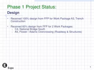
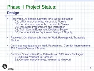
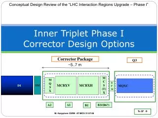
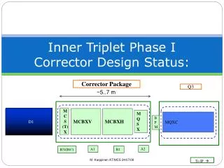
Triplet Layout LHC triplet • Issues: • Quadrupole length and powering • Orbit correctors • BPMS position • CP and QDXS length and D1 position Phase-1 triplet
Optics issues Insertions. The strength and aperture of the magnets are the limiting factors for reducing b*. Arcs. Correction of aberrations requires re-phasing of all the arcs and insertions for b* < 0.5 m. Triplets. Parasitic dispersion in the triplets due to large crossing angle has to be controlled. Beam crossing schemes in IP1 and IP5 need to be flexible. No dispersion suppressors in the vertical plane. Symmetry of the two IRs has to be maintained. A complete solution for the new LHC optics has been developed.
Magnet Cooling Quadrupoles and correctors: Pressurised static superfluid He bath at 1.3 bar, cooled by two-phase flow of saturated superfluid helium in a bayonet heat exchanger. Heat exchanger dimensioned for the ultimate power of 500 W/1.9 K and ultimate vapour velocity of 7 m/s. Due to the distance of the QRL (3.3 km), the temperature at high heat load increases from the outlet of the refrigerator (1.776 K) to 1.97 K on the coil surface. D1 dipole: Pressurised static superfluid He bath at 1.3 bar, cooled by heat conduction to the triplet (enough thermal margin) Beam screen: Cooled with supercritical helium, 5-20 K.
Triplet Cooling Scheme • Main features: • Control and safety valves integrated in the new service module QDXS. • Warm-up of the triplet independent of the arc. • Warm-up of the SC link/DFX independent of the triplet.
MQXC Low-b Quadrupole Coil aperture 120 mm Gradient 127 T/m Operating temp 1.9 K Current 13.8 kA Inductance 5.2 mH/m Yoke ID 260 mm Yoke OD 550 mm LHC cables 01 and 02 Enhanced cable polyimide insulation Self-supporting collars Single piece yoke Welded-shell cold mass
MCXB Dipole Corrector • Coil aperture 140 mm • Field strength 1.5 Tm • Operating temp 1.9 K • Current 2.4 kA • Inductance 12 mH • Yoke OD 550 mm • New 4 mm cable design • Cable polyimide insulation • Self-supporting collars • Single piece yoke • Welded-shell cold mass
D1 Separation Dipole • Two optimised RHIC DX magnets assembled in one helium vessel • Coil aperture 180 mm • Field 4.1 T • Magnetic length 7.4 m • Operating temp 1.9 K • Current 6.35 kA • Inductance 98 mH • Yoke OD 650/550 mm
Protection Against Particle Debris Triplet shielding efficiency: Phase-1 = 2.5 LHC • Protection against particle debris is the • single most serious issue of the upgrade. • Energy deposition in the coils and magnet lifetime. • Equipment protection around the beamline (TAS, TAN). • Protection of electronic equipment in underground areas. • Maintenance and interventions … Average dose 1.5 MGy/100 fb-1 All equipment built for a lifetime of 1000 fb-1, compatible with the lifetime of ATLAS (700) and CMS before their “Phase-2” upgrade.
Powering Equipment in IR1 • Split powering chosen as a compromise between volume and complexity. Protection of the magnets ensured by the energy extraction system and by the quench heaters. DFX, converters and switches located in low-radiation areas. DFX connected to the QDXS service module via a SC link (~30-100 m.) DFX DFX Link Cryo Link DSX Length ~28 m 3 sharp (~ 1.5 m radius) bends plus some curves Service Module (QDXS)
Conclusion A conceptual design for the Phase-1 Upgrade, in line with the general constraints, is at hand. The technical design, the limited R&D and tooling preparations for magnet construction, are advancing. Due to the fact that the LHC dipole cable is readily available, the magnets and other equipment can be built, under reasonable assumptions, by the end of 2014. However, conflict of resources needed for LHC consolidation. Deliverables, in particular for WP-6 have to be reviewed with respect to changed boundary conditions, resources, and newly identified technical challenges The available resources at CERN and worldwide for the construction of the magnets and other equipment for the Phase-1 Upgrade are limited. The collaborations with European and US laboratories, which bring in their expertise and resources, have been formalised and are in effect.