Download
1 / 6
60 likes | 464 Views
SP6003 in Flyback Synchronous Rectifier.

E N D
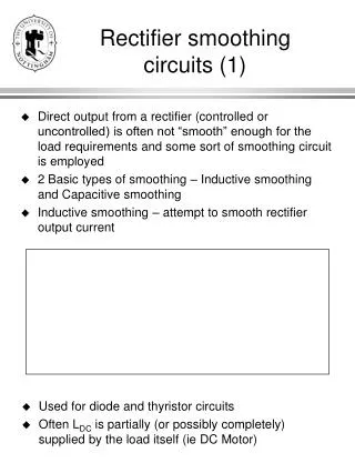
Before the introduction of Synchronous Rectifier Controller IC (SP6003), the use of SR in a Flyback converter is difficult. Traditional self-driven SR control in a Flyback often result in a relatively large reverse SR conduction, discharging the output capacitor at the beginning of every cycle. This leads poor efficiency, increased EMI noises, and at worst, possible destruction of the converter. A simple SP6003 can be used to easily control SR in a flyback without the complications. A flyback with SP6003 has full SR gate signal and prevents SR reverse conduction in CCM, DCM and N+1 power systems.
A. SP6003 in CCM The Synchronous Rectifier Flyback Converter Controlled by SP6003 in the CCM (heavy load). Notice that there is no reverse conduction, and the secondary S.R. received full width gate drive during S.R. conduction. (on 1us/div time scale) Vds (S.R.) 5V/Div (top) Vgs (S.R.) 5V/Div Vgs (primary) 10V/Div Ids (primary) 5A/Div (bottom)
B. SP6003 in DCM The Synchronous Rectifier Flyback Converter Controlled by SP6003 in DCM (light load). Notice that there is no reverse conduction current, and the S.R. gate received full width gate drive. (on 1us/div time scale) Vds (S.R.) 5V/Div (top) Vgs (S.R.) 5V/Div Vgs (primary) 10V/Div Ids (primary) 5A/Div (bottom)
C. SP6003 in Boundary of CCM & DCM The Synchronous Rectifier Flyback Converter Controlled by SP6003 on the boundary of CCM (heavy load) and DCM (light load). Notice that there is no reverse conduction, and the secondary S.R. received full width gate drive during S.R. conduction. (on 4us/div time scale) Vds (S.R.) 5V/Div (top) Vgs (S.R.) 5V/Div Vgs (primary) 10V/Div Ids (primary) 5A/Div (bottom)
D. SP6003 in no-load The Synchronous Rectifier Flyback Converter Controlled by SP6003 in no load. Notice that there is no reverse conduction current. (on 1us/div time scale) Vds (S.R.) 5V/Div (top) Vgs (S.R.) 5V/Div