Download

1 / 29
290 likes | 446 Views
Bridge 2153 Final Report. Premier Engineering Rose-Hulman Institute of Technology. Premier Engineering Team. Jake Vieck – Project Editor John Groff – Project Engineer Lauren Oakley – Client Liaison Cassidy Sutton – Project Manager Fred Lintz – Project Engineer. Overview.

E N D
Bridge 2153 Final Report Premier Engineering Rose-Hulman Institute of Technology
Premier Engineering Team • Jake Vieck – Project Editor • John Groff – Project Engineer • Lauren Oakley – Client Liaison • Cassidy Sutton – Project Manager • Fred Lintz – Project Engineer
Overview • Project Description • Design Requirements • Project Approach • Design Solution
Project Description (1) • Naval Support Activity (NSA) Crane • Located in Martin County, Indiana on 100 square miles • Employs nearly 4000 people (2nd largest employer in Southwestern Indiana) • Constructed in the early 1940s
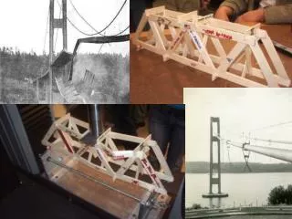
Project Description (3) • Carries H-161 over Boggs Creek • Constructed in 1942 • Partially reconstructed in 1986 • Total length ~ 76 ft • Total width ~ 24 ft • Travel width ~ 22 ft
Project Description (4) • Two-year inspections indicate need for replacement of Bridge 2153 • Holes in timber from insect damage • Corrosion on underside of deck • Poor wing wall pile condition • Severe checking
Design Constraints • Have minimum 60-yr life • Pass the 100-yr flood • Have only one span if economically feasible • Have low maintenance cost • Meet or exceed INDOT and AASHTO standards • Minimize cost
Client Requirements & Project Approach • Determine and assess design options • Recommend most desirable option • Design of replacement structure and approaches • Provide detailed construction plans and cost estimate • Provide necessary permitting information
Existing Conditions • Site assessment • Maps • Soil survey • Wetlands • Floodplain ` `
Bridge Material Options • Materials • Prestressed concrete • Concrete box culvert • Steel • Timber • Basis of Consideration • Initial cost • Lifespan • Maintenance cost • Constructability • Aesthetics
Geotechnical Investigation N BRIDGE
Geotechnical Investigation Elevation (feet)
Hydrologic Study • Drainage Area: DA = 2.58 sq mi • Slope: SL = 69.1 ft/mi • 100-yr flow rate: Q = 1910 cfs
Hydraulic Study • 100-yr flood elevation: 478 ft • Proposed bridge lowers 100-yr elevation by 0.11 ft
Structural Design • Standard 33” INDOT parapets • 8” cast-in-place concrete deck • 5 Type I bulb-tee prestressed concrete girders
Highway Design & Sight Distance 1.5” (165 lb/sy) Surface HMA 2.5” (275 lb/sy) Intermediate HMA 8” (880 lb/sy) Base 24” Compacted Aggregate Base
Highway Design & Sight Distance 1’ HMA PAVED SHOULDER PARAPET 10’ DRIVING LANE 11’ EXPANSION JOINT DRIVING LANE 10’ 11’ 2’ CONCRETE SHOULDER No. 53 STONE GUARDRAIL
Summary • Project Description • Design Requirements • Project Approach • Design Solution