Download
1 / 24
240 likes | 352 Views
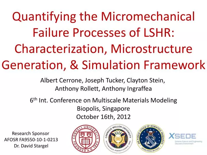
Quantifying the Micromechanical Failure Processes of LSHR: Characterization, Microstructure Generation, & Simulation Framework. Albert Cerrone , Joseph Tucker, Clayton Stein, Anthony Rollett , Anthony Ingraffea 6 th Int. Conference on Multiscale Materials Modeling Biopolis , Singapore

E N D
Quantifying the Micromechanical Failure Processes of LSHR: Characterization, Microstructure Generation, & Simulation Framework Albert Cerrone, Joseph Tucker, Clayton Stein, Anthony Rollett, Anthony Ingraffea 6th Int. Conference on Multiscale Materials Modeling Biopolis, Singapore October 16th, 2012 Research Sponsor AFOSR FA9550-10-1-0213 Dr. David Stargel
Overview • LSHR (low solvus, high refractory) disk alloy • nickel-based superalloy • low solvus • contributes to resistance to crack quenching • high refractory • high tensile strength and creep resistance • processed via powder metallurgy • used in disks of gas turbine engines • Methodology • quantify microstructurally small fatigue cracks (MSFCs) • improve safe life design • aid in development of next generation materials • by producing high fidelity, 3D finite element models of microstructures • from advanced characterization techniques (3D non-destructive orientation mapping) • and simulated in a HPC environment using a crystal plasticity framework 20μm LSHR
Outline • The Workflow • characterization • EBSD • HEDM • microstructure generation • reconstruction • synthetic generation • meshing • surface • volume • constitutive modeling • crystal plasticity • simulation • Case Study: Crack Initiation Induced • by Coherent Σ3 Twin Boundaries • Future Work 600μm 200μm
Characterization CCD camera lens • Scanning Electron Microscopy (w/ EBSD) • electron backscatter diffraction • used to detect crystallographic orientations • often coupled with serial sectioning, a • destructive method • High Energy X-Ray Diffraction Microscopy (HEDM) • orientation mapping in 3D • spatial information, as well • nondestructive • the high energy x-rays are uniquely able to • penetrate high-Z, fully dense materials X-ray beam EBSD Map Pole Figures Detector stage Sample stage Rotation stage
Characterization wire EDM’dspecimen sample 3mm EBSD-HEDM Comparison HEDM 100μm IPF Coloration EBSD 10μm loading direction to our knowledge, first time MSFC located within a 3D non-destructive orientation map 100μm
Microstructure Generation • Two Options • reconstruction (authentic representation) • align sections • segment grains • synthetic generation (statistically representative) • DREAM.3D • The voxelated microstructure is then meshed for simulation. voxelated grains containing crack entire volume 600μm
Meshing • Surface Meshing • multiple-material marching cubes algorithm • generated with the constraint of conformal boundaries • each grain’s mesh contained in STL file • must volume mesh each grain for 3D FE analysis • Volume Meshing • meshing algorithm • octree generation • advancing front procedure • mesh improvement • back-tracking • smoothing • mesh quality gauged with • tetrahedron shape metric * • Parallelized PolycrystalMesher (PPM) • exposes FRANC3D and ABAQUS meshing routines • used to mesh synthetic micros of nacre, R88DT, LSHR, AA7075-T651 • available at http://www.cfg.cornell.edu/~arc247/PPM/ degenerate = 0 equilateral tet = 1 * Freitag and Knupp, 1999, 8th International Meshing Roundtable.
Crystal Plasticity • rate, temperature, and grain size sensitive * • 12 FCC octahedral and 6 FCC cubic (high temperature) slip systems • resolved shear stress • flow rule • hardness evolution • smaller grains implicitly hardened via ΔiJterm in hardness evolution • smaller grains explicitly hardened via Hall-Petch • dislocations pile up at grain boundaries • in smaller grains, greater stress required to move dislocations across boundaries • higher applied stress, higher yield strength * Matouš and Maniatty, 2004, IJNME
Case Study: Crack Initiation Induced by Coherent Σ3 Twin Boundaries
MSFC Characteristics • Nucleation • microcracks nucleate close to coherent Σ3 twin boundaries • twin boundaries are in large, high Schmid factor (soft) grains • Propagation • microcracks propagate along Σ3 twin boundaries • predominant mechanism is transgranular • cracks arrest at highly misoriented grains • MSFCs confined to pockets of low misoriented grains René88DT twin = 1, matrix = 2 20μm image from Miao, Pollock, Jones, 2009, Acta Mater.
Nucleation (Hot-Spot ID) Σ3 boundary 75μm Loading • twin embedded in ALA grain • ALA grain assigned high Schmid factor (soft) • ALA grain – nearest neighbor misorientations < 20o • 35 steps of smoothing • 10-mil DOFs 0.5% - 1.0% Applied Strain
Future Work • The Workflow • 3D, nondestructive characterization • microstructure generation / reconstruction • surface and volume meshing • crystal plasticity model formulation • simulation • Predict nucleation event in microstructures using slip-based damage metrics which follow from crystal plasticity formulation. • Determine microstructural dependence on MSFC driving forces. • Determine microstructural dependence on MSFC propagation rate law.
Microstructure Generation • DREAM.3D * • microstructure processing and generation • synthetic microstructure generation • input (from characterization) • misorientation / orientation • aspect ratio • grain size distribution (GSD) • closed volume packed with ellipsoids representative of GSD • simulated annealing optimizes packing • cellular automaton nucleates and grows ellipsoids • voxelated microstructure output • reconstruction • can be used to align, clean, and reconstruct slices of data from serial sectioning and HEDM 42.5μm * dream3d.bluequartz.net
Computational Specifics • Finite Element Driver • Finite Element All-Wheel Drive (FEAWD) • scales to 1,024+ cores • built on PETSc, HDF5, and FEMLib • Computational Resource • Ranger (XSEDE resource from Texas Advanced Computing Center) • Performance 92-sec speedup plot 12.8-mil DOFs 113-sec Speedup 394-sec Number of Nodes (16 cores per node)
Shape Metric metric ea,bis an edge vector from vertex a to vertex b of the tetrahedron ndenotes the vertex number Wis the Jacobian of the linear transformation between a unit equilateral tetrahedron and the reference configuration
HEDM 50-100 kilo-electron volt X-ray beam Beam illuminates thin plan section of sample Bragg spots are imaged on CCD detectors Measuring a set of spots from multiple sample-to-detector distances yields the position of the diffracted grain
Material State Mapping CP model asserts volume preserving plastic deformation. multiplicative decomposition
ΔCTD Criterion da = crack growth increment dN = cycle increment ΔCTD = cyclic change in crack tip displacement ΔCTDcritical= minimum crack tip displacement required for propagation G = material constant (0.3-0.5, dependent on material, strain, and strain ratio) Crack opening is the dominant MSFC propagation rate mechanism in Stage II. Stage I: sliding dominated: along the slip systems(s) most favorably aligned with the direction(s) of maximum shear stress Stage II: opening dominated: in the direction normal to maximum tangential stress ahead of the crack front blunting: the cyclic change in crack displacement near the crack tip (CTD)
Schmid Factor critical resolved shear stress applied stress angle between loading direction and slip plane normal angle between loading direction and slip direction
Voce-Kocks Voce Law σ macroscopic true stress ε true plastic strain σs saturation stress extrapolated to zero work-hardening rate σo initial or threshold stress at which homogeneous plastic deformation begins to be appreciable Kocks temperature and strain rate
The Saltykov Method to Predict 3D Grain Size Distributions • alternative to linear-intercept and sphere-equivalent methods • predicts grains per unit volume from grains per unit area • assumes all grains are spheres • grains assumed equiaxed 2D map to estimate 3D grains • grain sizes are binned based on intersection probability of a sphere with a section plane
Volume Meshing • octree generation • constructed around the grain • refined to the element sizes of the surface mesh, and then to the largest cell size on the boundary • advancing front • meshes inward from boundary, discretizing volume with quadratic tetrahedra • facets on grain boundary unchanged, preserving conformity between adjacent grains • mesh cleaning • smoothing • back-tracking