Download
1 / 64
640 likes | 792 Views
Faculty of Electrical Engineering. Lecture : En. Syahrom Bin Zakaria. Basic 3D Drawings. X - a positive value pointing to the right on the screen; Y - a positive value pointing up on the screen; and Z - a positive value pointing straight at the user in 3D space.

E N D
EC202 COMPUTER AIDED DESIGN Faculty of Electrical Engineering Lecture : En. Syahrom Bin Zakaria Basic 3D Drawings
X - a positive value pointing to the right on the screen; Y - a positive value pointing up on the screen; and Z - a positive value pointing straight at the user in 3D space. IMPORTANT 3D TERMINOLOGY
Horizontal plane; Frontal plane; Profile plane; Oblique plane; and Inclined plane. The possible planes use in CAD drawings
Wireframe; surface; and Solid TYPE OF 3D MODELS
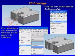
Methods Of Creating 3D Solid Models • Extruding a 2D Object Object in 2D view Object after Extrude
Revolving an Object about a Cylindrical Axes • From the pull down menu select Draw – surface – revolved surface as shown
Select the object to be revolve and define the axis of revolution
Using the Basic Primitives Can you name these primitive shapes?
Drawing of 3D Primitives • BOX UCS at X rotate 900 At World UCS
Wedge • UCS World
Wedge • UCS X rotate 900
Cylinder • UCS World
3D EDITING COMMANDS • BOOLEAN OPERATION UNION
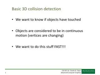
INTERFERE INTERFERE is an identifier command. It identifies (highlights) the area where two selections of 3D solids overlap and gives you the option to create a new 3D solid from the overlapping volume. 3D Editing Commands
Is similar to the command for 2D drawings. FILLET and CHAMFER
Chamfering an object • For chamfering an object as shown below, you must enter command “Chamfer”. • Select the distance of chamfering or angle in the command prompt (the example to you is a distance). • Select edge to be chamfer
Enter distance of chamfering in this example: The 1st dist. is 20mm, 2nd dist is 30 mm
Fillet an object • First enter the command “fillet”, • Enter the radius (20mm in example), • Select the the edge to be fillet,
3D Draw Commands • SECTION
USER COORDINATE SYSTEM (UCS) in 3D • UCS toolbar WCS 3 point
Using UCS 3 point • To draw a circle in an inclined surface Y.
Specify new origin point; • Specify point on positive X-portion; • Specify point on positive Y- portion
Solview is a command provide another method of setting up orthographic views and it is superior to some of the options because it setup layers according to your named view. To implement solview, work in the multistep process: 1. Create a 3D solid modeling, What is SOLVIEW
Choose layout 1 from the bottom of drawing window as shown Layout1 (layout tab)
Page setup dialog box will appear Change paper size if necessary Then, Click ok
A 3d view will appear like as follow: Delete this view first
Command : solview (enter) Enter an option [Ucs/Ortho/Auxialiary/Section]: Ucs (enter) [Named/World/?/Current]<Current>: (press Enter) Specify view center<specify viewport>: (pick any point, the top view will appear, then press Enter) Specify first corner of viewpoint: (use window to pick the points.) Enter view name: top (press Enter) From here, enter “solview” at commnad prompt.
Enter an option [Ucs/Ortho/Auxialiary/Section]: ortho [Named/World/?/Current]<Current>: (press Enter) Specify view center<specify viewport>: (pick any point, the top view will appear, then press Enter) Specify first corner of viewpoint: (use window to pick the points.) Enter view name: front (press Enter) To create the front view
Pick from midpoint as shown Midpoint of border