Download
1 / 56
560 likes | 767 Views
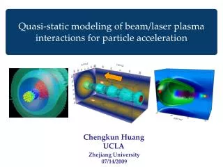
UCLA. SciDAC plasma-based team:. W.B.Mori UCLA F.S.Tsung CK. Huang V.K.Decyk D.Bruhwiler TechX D.Dimitrov E.Esarey LBNL B.Shadwick G.Fubiani T.Katsouleas USC S.Deng. Advanced accelerator effort is highly leveraged: Big bang for the buck. Why and what is plasma-based acceleration.

E N D
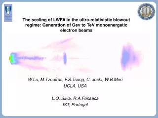
UCLA SciDAC plasma-based team: • W.B.MoriUCLA • F.S.Tsung • CK. Huang • V.K.Decyk • D.Bruhwiler TechX • D.Dimitrov • E.EsareyLBNL • B.Shadwick • G.Fubiani • T.KatsouleasUSC • S.Deng
Advanced accelerator effort is highly leveraged:Big bang for the buck
Why and what is plasma-based acceleration Long term future of High-Energy physics requires the need for new high-gradient technology Gradients from 1GeV/m to 100 TeV/m are possible from relativistic plasma waves
E-164/ORION LEP E-162 Experimental progress LBNL
- - - - - - - - - - - - - - - - - - - - - - - - - - - - - - - - - - - - - - - - - - - - - - - - - - - - - - - - - - - - - - - - - - - - - - - - - + + + + + + + + + + + + + + + - + + + + + + + + + + + + + + + - - - - - - - - - + + + + + + + + + + + + + + + + - - + + + + + - + + + + + - + + + + + + + + + + + + + + + - - - - + + + + + + + + + + + + + + + - - - - - - - - - - - electron beam - - - - - - - - - - - - - - - - - - - - - - - - - - - - - - - - - - - - - - - - - - - - - - - - - - - - Ez Physical Principles of the Plasma Wakefield Accelerator • Space charge of drive beam displaces plasma electrons • Plasma ions exert restoring force => Space charge oscillations • Wake Phase Velocity = Beam Velocity (like wake on a boat) • Wake amplitude • Transformer ratio
Concepts For Plasma Based Accelerators Pioneered by J.M.Dawson • Plasma Wake Field Accelerator(PWFA) • A high energy electron bunch • Laser Wake Field Accelerator(LWFA) • A single short-pulse of photons • Plasma Beat Wave Accelerator(PBWA) • Two-frequencies, i.e., a train of pulses • Self Modulated Laser Wake Field Accelerator(SMLWFA) • Raman forward scattering instability evolves to
Mission Develop high fidelity parallelized software (at least two distinct codes): primarily particle based models Model the full-scale of current experiments ~100MeV -1GeV Enable full-scale modeling of 100+ GeV plasma-based colliders Transfer plasma models to conventional accelerator modeling Enable scientific discovery
A goal is to build a virtual accelerator:A 100 GeV-on-100 GeV e-e+ ColliderBased on Plasma Afterburners 3 km 30 m Afterburners
Computational challenges for modeling plasma-based acceleration(1 GeV Stage): 1000hours/GFlop
Community of parallel PIC codes and algorithms exist:PIC codes make “minimal” physics approximations • Parallel Full PIC • OSIRIS • Vorpal/OOPIC • Parallel quasi-static PIC • quickPIC • Fluid (quasi-static and full) • To model a plasma stage including beam loading will require particle models
Computational cycle (at each step in time) Particle positions push particles weight to grid Lorentz Force t What Is a Fully Explicit Particle-in-cell Code? • Maxwell’s equations for field solver • Lorentz force updates particle’s position and momentum Interpolate to particles Typical simulation parameters: ~107-109 particles ~1-100 Gbytes ~104 time steps ~102-104 cpu hours
SciDAC collaborative approach • Multiple codes • Benchmarking against each other and against reduced numerical models and analytic theory • Validation against experiment • E-162/E-164 • L’OASIS • Modeling future experiments • E-164/E-164x • L’OASIS • A path towards a virtual accelerator • SCIENTIFIC DISCOVERY ALONG THE WAY
Parallel Code Development OSIRIS: full PIC Vorpal/OOPIC: full PIC quickPIC: reduced PIC UPIC: parallel PIC framework
UCLA OSIRIS.framework Basic algorithms are mature and well tested • Fully relativistic • Choice of charge-conserving current deposition algorithms • Boris pusher for particles, finite field solver for fields • 2D cartesian, 2D cylindrical and 3D cartesian • Arbitrary particle initialization and external fields • Conducting and Lindmann boundaries for fields; absorbing, reflective, and thermal bath for particles; periodic for both • Moving window • Launch EM waves: field initialization and/or antennas • Launch particle beam • particle sorting and ion subcycling • Extended diagnostics using HDF file output: • Envelope and boxcar averaging for grid quantities • Energy diagnostics for EM fields • Phase space, energy, and accelerated particle selection diagnostics for particles
Ionization modules are being added: Both in 2D and 3D Ionization modules were added in 2D (slab and cylindrical) and 3D Monte Carlo impact ionization model was used: particles are born at rest Monte Carlo field ionization model was used: particles are born at rest Various cross sections and tunnel rates are being tested: benchmarking with the help of OOPIC
Effort was made to improve speed and maintaing parallel efficiency:2D 128x128 with 16 particles/cell per processor and Vth=.1c Speed in 3D: 3.2ms/ps with 80%efficiency on 512 processors And 60% on 1024 processors
OSIRIS Algorithms Domain Decompositions • OSIRIS currently allows distribution of the simulated space into evenly partitioned • domains along any axis • next steps in extending the code will be to introduce an uneven distribution of • domains and dynamic load balancing: follow concepts in PLIB 1D Decomposition 2D Decomposition 3D Decomposition
VORPAL – Multi-dimensional hybrid code • Achieves great flexibility with negligible run-time penalty • Multi-dimensional (2D or 3D, with Cartesian geometry) • can switch from 2D to 3D with same code and input file • enabled by “generic programming” paradigm of C++ • Runs in serial or parallel (using MPI) • flexible 2D and 3D domain decomposition • good scaling up to 500 processors has been demonstrated • Cross-platform: Linux, IBM SP, Windows, Solaris • Combines multiple fluid and PIC algorithms seamlessly • finite-difference time domain (FDTD) on structured Yee mesh • Particle-in-Cell • standard Boris particle push • charge-conserving current deposition • Cold fluid algorithms • multiple flux-corrected transport (FCT) algorithms for positive density
VORPAL’s flexible domain decomposition allowsfull load balancing, good scaling • Beowulf: 1.2GHz Athlons, fast ethernet • Have seen good scaling on 128-256 SP processors General decomposition allows load balancing Domains down to 45x25x25 with 140k particles, 20% surf/vol Set theory based messaging
Moving Ionization Algorithms from OOPIC to VORPAL • OOPIC is a 2-D (x-y & r-z) electromagnetic PIC code • Includes Monte Carlo collision (MCC) models • These enabled rapid implementation of relativistic electron-impact and field-induced tunneling ionization algorithms • Uses MPI for parallel computing (1-D domain decomposition) • These ionization algorithms are being ported to VORPAL • OOPIC ionization algorithms have been validated against data from the l’OASIS lab at LBNL:
UCLA Wake Beam quickPIC • Quasi-static approximation: driver evolves on a much longer distances than wake wavelength • Frozen wakefield over time scale of the bunch length • => b and/or xR >> sz (very good approximation!)
Basic equations for approximate QuickPIC • Quasi-static or frozen field approximation converts Maxwell’s equations into electrostatic equations Maxwell equations in Lorentz gauge Reduced Maxwell equations Quasi-static approx. Local--f,A at any z-slice depend only on r,j at that slice!
QuickPIC loop (based on UPIC): 2-D plasma slab Wake (3-D) Beam (3-D)
Node 3 Node 2 Node 1 Node 0 x z y Node 3 Node 2 Node 1 y Node 0 x Parallelization of QuickPIC
Benchmarking Full PIC: OSIRIS and OOPIC particle drivers laser drivers Full PIC vs. quasi-static PIC: OSIRIS and quickPIC particle drivers PIC vs. Fluid: Laser drivers particle drivers Simulation against theory trapping mechanism in all optical injection
quickPIC vs. OSIRIS Positron driver Focusing Field (mcp/e) Longitudinal Wakefield (mcp/e) Head Tail Plasma density = 2.1E14 cm-3, Beam Charge = 1.8E10 e+ Wakefield and focusing field from QuickPIC agree well with those from Osiris, and it is >100 times faster!.
Benchmarking (2D) field ionization routines:OOPIC and OSIRIS
Modeling experiments: Code validation and interpretation of physics Plasma wakefield accelerator(PWFA) E-157/E-162 electron acceleration/focusing positron acceleration/focusing Laser wakefield accelerator(LWFA/SMLWFA) L’OASIS(LOA) Blue shifts self-trapped electrons
UCLA E-162 Plasma Wakefield Expt. Located in the FFTB FFTB Ionizing Laser Pulse (193 nm) Streak Camera (1ps resolution) e- or e+ ∫Cdt Li Plasma ne≈2·1014 cm-3 L≈1.4 m X-Ray Diagnostic N=2·1010 sz=0.6 mm E=30 GeV Quad+Bend Magnets Cerenkov Radiator (Aerogel) Optical Transition Radiators Dump 12 m
100 TW Ti:sapphire Under construction Laser beams 10 TW Ti:sapphire CCD Mirror Laser beam ebeam Electrons Gasjet Shielded target room High energy < 10 mrad Parabolic mirror Low energy 100 mrad Laser-plasma accelerator R&D at l’OASIS lab • Test bed for R&D concepts towards 1 GeV module of a laser accelerator and applications • Facility includes 10 TW, 50 fs laser system @ 10 Hz (100 TW under development) • Laser, plasma and beam diagnostics; radiation shielded experimental bays • Training ground for students and postdocs
Excellent agreement between simulation and experiment of a 28.5 GeV positron beam which has passed through a 1.4 m PWFA OSIRIS Simulation Prediction: Experimental Measurement: Peak Energy Loss 64 MeV 65±10 MeV Peak Energy Gain 78 MeV 79±15 MeV OSIRIS E162 Experiment Head Tail Head Tail 5x10⁸ e+ in 1 ps bin at +4 ps
Moving Ionization Algorithms from OOPIC to VORPAL • OOPIC is a 2-D (x-y & r-z) electromagnetic PIC code • Includes Monte Carlo collision (MCC) models • These enabled rapid implementation of relativistic electron-impact and field-induced tunneling ionization algorithms • Uses MPI for parallel computing (1-D domain decomposition) • These ionization algorithms are being ported to VORPAL • OOPIC ionization algorithms have been validated against data from the l’OASIS lab at LBNL:
State-of- the- art ultrashort laser pulse 0 = 800 nm, Dt = 35 fs I = 1x10¹⁹ W/cm-2, W =7 mm 300 cells 80 mm 300 cells 80 mm 2000 cells 80 mm Full scale 3D LWFA and SMLWFA simulations:L’OASIS parameters • Simulation Parameters • Laser: • a0 = 3 • wl/wp = 3 to 15 • Particles • 1x2x2 particles/cell • 200 million total • The parameters are similar to those at LOA and LBNL Laser propagation Plasma Background ne = 1.38-17 x1019 cm-3 Simulation ran for ~10000 time steps (~3 Rayleigh lengths)
In 3D the electrons have an asymmetric spot size in the plasma:laser effects accelerationwhat happens when they exit the plasma? (Electrostatic PIC combined with semi-analytical model: Fubiani) p3 vs. p1 p1 vs. x3 p3 vs. x2
Modeling planned experiments: Providing guidance Plasma wakefield accelerator(PWFA) E-164/E-164x high-gradient electron acceleration bunch length scaling ionization Laser wakefield accelerator(LWFA/SMLWFA) L’OASIS(LOA) all optical injection acceleration in channels
Benchmarking Longitudinal Wakefield (mcp/e) Head Tail Result from benchmark run with plasma density = 2.1E14 cm-3, beam charge = 1.8E10 e-. QuickPIC run with periodic boundary, Osiris run with conducting boundary.
Bunch length scaling: E164 and Afterburner parameters
Pulse distortion leads to a second phase of acceleration
Modeling a 5TW 50 fs laser propagating through 60 Raylengths in a plasma channel
Fluid Code: Laser pulse in a channel • 2D Fluid-Maxwell Code • Relativistic and nonlinear • No averaging: laser oscillations resolved • Moving window • Detailed comparisons to particle codes in progress • Example: Laser pulse in a plasma channel • Wakefield generation • Laser pulse energy depletion • Frequency red-shifting • Parameters: Achievable at the l’OASIS lab
Laser Wakefields in Plasma Channel Benchmarking against PIC is beginning Density vs (x,z) Nonlinear plasma wave wpt = 240 (0.9 mm) Back Longitudinal Electric Field vs (x,z) Front
Research focus: How can one inject particles into accelerating region of phase space? All require moving particles to accelerating/focused region in phase space Investigating multiple methods for optical inject, those of others and ours • LILAC • Beat wave (LBNL) • Phase kick (result of this research) F+Fp gv z-vgt
Discovery: The expansion of the focusing region for nonlinear wakes improves trapping mechanism Ey • Focusing region greatly expanded • Focusing trajectories exists for positive potential • Consequence: small phase kick can trap particles F
Simulations show that focusing collimation forms the beam • Region of negative potential energy is focusing • Region of negative phase relative to minimum is accelerating • Particles stay in this region while accelerating provided they are inside the F/D transition invariant curve • Place large population of particles just inside this curve and dynamics forms beam after 1/4 of synchrotron (bounce) oscillation 66 px/c y x Laser propagates along x Overplotting shows beams worse than they are Simulations showing secondary beams
Beyond planned experiments: Afterburner modeling Nonlinear wakes preformed self-ionized Nonliear beamloading Stability: hosing Final focusing
OOPIC shows that a PWFA e- driver can ionize neutral Li • OOPIC simulations show that tunneling ionization plays a key role in the PWFA afterburner concept • The self-fields of the bunch can ionize Li or Cs • High particle density (i.e. large self-fields) is required to drive a strong wake • In Li, a shorter afterburner drive beam could ionize the plasma by itself • This approach would greatly simplify beam-driven wakefield accelerators • sr=20 mm; sz=30 mm; 2x10¹⁰ e- in the bunch; E0=11.4 GV/m • We need to model evolution of the drive beam with TI effects included
1+1 ≠ 2:Superpostion cannot be used for nonlinar beamloading Linearsuperposition Nonlinear wake 2nd beam charge density 1st beam charge density Nonlinear wake
- - - - - - - - - - - - - - - - - - - - - - - Er - - - - - - - - - - - - - - - - - - - - - - - - - - - - - - - - - - - - - - - - - - - - - - - - + + + - - - - - - - - - + - - + + + + + - + + + + + - + + + + + + + - - - - + + + + + + + + + + + + + + + - Ez - - - - - - - - - - - - - - - - - - - - - - - - - - - - - - - - - - - - - - - - - - - - - - - - - - - - - - - - - - - - - + + + + + + + + + + + + + + + + + + + + + + + + + + + + + + + + + + + + + + + + + + + + + + + + + + Hosing can be studied for afterburner parameters using quickPIC Acceleration field Focusing field t = 0 t = 64,800 (1/p) 3D image of the plasma charge density under blow-out regime Electron drive beam hoses as it propagate over a long distance in the plasma
Connections to other areas in accelerator modeling electron-cloud modeling using plasma codes: quickPIC Beam-Beam codes use parts of UPIC: UPIC is a parallel PIC Framework (it incluces PLIB)which is a general computer science component to this project