Download
1 / 46
500 likes | 719 Views
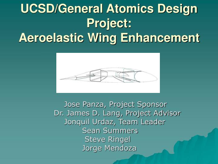
UCSD/General Atomics Design Project: Aeroelastic Wing Enhancement. Jose Panza, Project Sponsor Dr. James D. Lang, Project Advisor Jonquil Urdaz, Team Leader Sean Summers Steve Ringel Jorge Mendoza. Presentation Outline:.

E N D
UCSD/General Atomics Design Project:Aeroelastic Wing Enhancement Jose Panza, Project Sponsor Dr. James D. Lang, Project Advisor Jonquil Urdaz, Team Leader Sean Summers Steve Ringel Jorge Mendoza
Presentation Outline: • Goals, Schedule, & Actual Cost • Active Camber Change • Aircraft Characteristics • Aircraft Initial Performance • Methods of Altering Airfoil • Effects of Altering Airfoil • Final Performance • Propulsion • Control Reversal • Stability & Control • Materials & Structure • Cost Estimates • Conclusions • References & Acknowledgements
Goals: • Originally: Create flutter suppressant design • After research and advice from Professors-new goal • New Goals: Increase performance and roll efficiency with active camber change and control reversal
Schedule: • Flutter research (3 weeks) • Thunder and control reversal research (3 weeks) • Analysis and data collection (2 weeks) • Finalize analysis, conclusions, and presentation preparation (2 weeks)
Current Cost • Engineering hours and transportation costs • Total current cost $37,863.00
Active Camber Change: Original Airfoil Positively Deflected Airfoil Negatively Deflected Airfoil
Aircraft Characteristics: • TOGW = 10,500 lbs • T/W = 0.14 • W/S = 33.33 • Span = 84 feet • Sweep = 2.36 degrees
Aircraft Initial Performance: Loiter 52,000 feet • Max Air Speed = 220 knots • Cruise Velocity = 144 knots • Loiter = 127 knots Cruise Out Cruise Back 25, 000 feet 38 hours 3,900 nm 4,000 nm
Methods of Altering Airfoil: Thunder-Piezoelectric Actuator • Less power required to actively change camber • Compact • Easy to Install • Alternative = Spar Twisting
Airfoils: Tip Original Airfoil Positively Deflected Airfoil Max thickness: t/c = 0.15 Camber = 0.05 @40%chord Negatively Deflected Airfoil Max thickness: t/c = 0.16 Camber = 0.06 @43%chord Max thickness: t/c = 0.14 Camber = 0.04 @34%chord
Airfoils: Root Original Airfoil Positively Deflected Airfoil Max thickness: t/c = 0.17 Camber = 0.05 @40%chord Max thickness: t/c = 0.19 Camber = 0.06 @47%chord Negatively Deflected Airfoil Max thickness: t/c = 0.15 Camber = 0.04 @34%chord
Effects of Altering Airfoil:Theoretical Lift Coefficient vs Angle of Attack
Effects of Altering Airfoils:CD0 vs Mach Number At 25,000 feet At 52,000 feet
Effects of Altering Airfoil:K vs Mach Number At 25,000 feet At 52,000 feet
Effects of Altering Airfoil: Drag Polar 52,000feet - Loiter Speed Drag Polar 25,000feet-Cruise Speed
Effects of Altering Airfoils: CL vs L/D at Cruise CL vs L/D at Loiter
Effects of Altering Airfoils:Fuel Burned vs. Drag At 25,000 feet At 52,000 feet
Final Performance: Increased Performance: Loiter time = +1 hour Cruise Back = +400 nm Fuel = -200 lbs. to complete initial mission profile Loiter 52,000 feet Cruise Out Cruise Back 25,000 feet 39 hours 4,300 nm 4,000 nm
Propulsion: Turboprop Engine • Based on Assumptions from Raymer:
Control Reversal Increasing Roll Effectiveness Utilizing Wing Twist due to Control Surface Reversal
Stability and Control • Control reversal • Roll effectiveness • Lateral control governed by control system • Control surface sizing • Aerodynamic center • Divergence speed • Flutter speed
Control Reversal • Actively control wing twist • Increase roll-rate performance • Damp out potential flutter excitations • Decrease deflection of wing • Specific applications of AAW in recent design studies have shown AAW technology to provide a 7 to 10% reduction in aircraft takeoff gross weight (TOGW) for subsonic cruise and Joint Strike Fighter type configurations, while a 20% reduction can be realized in TOGW for a supersonic cruise configuration.
Control Reversal: Negative Twist using Flaps and Ailerons Positive Twist using Ailerons and Slats
Control Benefits/Issues of AAW • If AAW works, then structural weight can be removed that was otherwise needed to make the wing stiff. Also, the wing could have a higher aspect ratio, which would normally make it too flexible. Higher aspect ratio should reduce drag, and combined with lower weight should improve payload-range performance. Boeing Sonic Cruiser officials have shown interest in the technique. • The lurking concern is flutter. This is a reason the preproduction F-18A design was chosen; its flight test showed that even though the wing was flexible, it did not have a flutter problem--hopefully removing this concern from the AAW. There is no active flutter suppression in the planned AAW control laws.
Roll Performance • Less lateral moment of inertia of wing due to lighter wing • Twisting wings will allow better flow control over wing surface thus generating more lift and reducing drag • Creates a more efficient wing during maneuvering • Decreases the parasitic drag caused by control surfaces with rigid wing • Uses traditional roll generation methods until dynamic pressures are high enough to twist wing with control reversal • Above switch occurs in control law (future work)
Control Surface Sizing • Must generate enough torque to twist the wing as desired • Control surfaces will be used to damp out excitations that could lead to flutter • Leading edge and trailing edge devices used in main part of wing • Trailing edge surface only on wingtip
Aerodynamic Center • Aerodynamic center is reference point for pitching moment calculations • Flight conditions are always subsonic for Mariner • Aerodynamic center can be assumed to be located at quarter-chord of Mean Aerodynamic Chord.
Divergence Speed • Designed new wing to have the same divergence speed as current design. • Sea level • Safety factor = 1.25
Materials and Structures • Material Selection • Sources and estimates of limit loads • Structural concept • Wing shear and bending moment diagram approximations • Ixx, Iyy, J
Material Selection • Similar materials as current design • 95% of aircraft is composites • Composite properties • Utilize bend-twist coupling with layup • General dimensions of current design conserved
Aerodynamic Loads • Loads/Boundary Conditions • Flat plate Aero modeling
Structural properties • Wing approximated as cantilevered beam with constant cross-sectional area • Moments of inertia for airfoil cross section • Torsional Stiffness of Wing
Limit Loads • Maneuvering loads • Gust loads • Control deflection • Take-off and landing loads • Power plant loads • Load factors approximately 3 to 4
Shear & Bending Moment Diagrams • Lift load approximated as point load acting at aerodynamic center of wing.
Structural Geometry • Span • MAC • Spar locations • Set up (spars skin) no ribs or stringers
Material Cost • Cost of Thunder actuator per aircraft: $170,861.48
DAPCA IV Model • Estimated Flyaway and RDT&E costs per aircraft for a 100 aircraft buy.
System Configuration Improvements • Iterate to find optimal skin thickness • Determine optimal spar dimensions and locations • More improvements can be made after test results are considered and analyzed
Cost Improvement • Wait for the technology to mature • Make a special contract with supplier to purchase Thunder actuators at a lower cost • Lower drag will increase efficiency and lower operational costs
Conclusions: • Results: Not worth the extra cost for Mariner • Would be more profitable for a Hunter/Killer • Planes today do not operate at max efficiency – with increased technology this design will become the more profitable method to increase performance
Future Work Needed: • Active Camber Change: • Research into Angle of Attack vs. Laminar Flow • Control Reversal: • Finite Element Model and Analysis • Test article fabrication • Flight Testing • Active flutter suppression in the planned AAW control laws.
References & Acknowledgements: • Josh Adams • Dr. John Kosmatka • John Meisner • Raymer, Daniel P., “Aircraft Design: A Conceptual Approach” • Anderson, “Fundamentals of Aerodynamics” • NASA Paper • AIAA Paper • Beer, Ferdinand P., “Mechanics of Materials”


![Crafting Rich Experiences with Progressive Enhancement [Beyond Tellerrand 2011]](https://cdn4.slideserve.com/7565246/crafting-rich-experiences-with-progressive-dt.jpg)
![There Are No “Buts” in Progressive Enhancement [Øredev 2015]](https://cdn4.slideserve.com/7568391/slide1-dt.jpg)