Download
1 / 29
290 likes | 302 Views
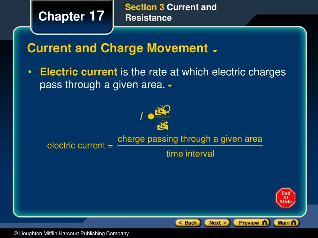
Section 3 Current and Resistance. Chapter 17. Current and Charge Movement. Electric current is the rate at which electric charges pass through a given area. Section 3 Current and Resistance. Chapter 17. Conventional Current. Click below to watch the Visual Concept. Visual Concept.

E N D
Section 3 Current and Resistance Chapter 17 Current and Charge Movement • Electric currentis the rate at which electric charges pass through a given area.
Section 3 Current and Resistance Chapter 17 Conventional Current Click below to watch the Visual Concept. Visual Concept
Section 3 Current and Resistance Chapter 17 Drift Velocity • Drift velocityis the the net velocity of a charge carrier moving in an electric field. • Drift speeds are relatively small because of the many collisions that occur when an electron moves through a conductor.
Section 3 Current and Resistance Chapter 17 Drift Velocity Click below to watch the Visual Concept. Visual Concept
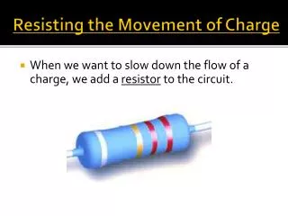
Section 3 Current and Resistance Chapter 17 Resistance to Current • Resistanceis the opposition presented to electric current by a material or device. • The SI units for resistance is the ohm (Ω) and is equal to one volt per ampere. • Resistance
Section 3 Current and Resistance Chapter 17 Resistance to Current, continued • For many materials resistance is constant over a range of potential differences. These materials obey Ohm’s Law and are calledohmic materials. • Ohm’s low does not hold for all materials. Such materials are callednon-ohmic. • Resistance depends on length, cross-sectional area, temperature, and material.
Section 3 Current and Resistance Chapter 17 Factors that Affect Resistance Click below to watch the Visual Concept. Visual Concept
Section 3 Current and Resistance Chapter 17 Resistance to Current, continued • Resistors can be used to control the amount of current in a conductor. • Salt water and perspiration lower the body's resistance. • Potentiometershave variable resistance.
Chapter 17 Section 4 Electric Power Objectives • Differentiatebetween direct current and alternating current. • Relateelectric power to the rate at which electrical energy is converted to other forms of energy. • Calculateelectric power and the cost of running electrical appliances.
Chapter 17 Section 4 Electric Power Sources and Types of Current • Batteries and generators supply energy to charge carriers. • Current can be direct or alternating. • In direct current, charges move in a single direction. • Inalternating current, the direction of charge movement continually alternates.
Chapter 17 Section 4 Electric Power Energy Transfer • Electric power is the rate of conversion of electrical energy. • Electric power P = I∆V Electric power = current potential difference
Chapter 17 Section 4 Electric Power Energy Transfer Click below to watch the Visual Concept. Visual Concept
Chapter 17 Section 4 Electric Power Energy Transfer, continued • Power dissipated by a resistor • Electric companies measure energy consumed inkilowatt-hours. • Electrical energy is transferred at high potential differences to minimize energy loss.
Section 1 Schematic Diagrams and Circuits Chapter 18 Schematic Diagrams • A schematic diagram is a representation of a circuit that uses lines to represent wires and different symbols to represent components. • Some symbols used in schematic diagrams are shown at right.
Section 1 Schematic Diagrams and Circuits Chapter 18 Schematic Diagram and Common Symbols Click below to watch the Visual Concept. Visual Concept
Section 2 Resistors in Series or in Parallel Chapter 18 Resistors in Series • Aseriescircuit describes two or more components of a circuit that provide a single path for current. • Resistors in series carry the same current. • Theequivalent resistancecan be used to find the current in a circuit. • The equivalent resistance in a series circuit is thesum of the circuit’s resistances. Req = R1 + R2 + R3…
Section 2 Resistors in Series or in Parallel Chapter 18 Resistors in Series
Section 2 Resistors in Series or in Parallel Chapter 18 Resistors in Series, continued • Two or more resistors in the actual circuit have the same effect on the current as one equivalent resistor. • The total current in a series circuit equals the potential difference divided by the equivalent resistance.
Section 2 Resistors in Series or in Parallel Chapter 18 Sample Problem Resistors in Series A 9.0 V battery is connected to four light bulbs, as shown at right. Find the equivalent resistance for the circuit and the current in the circuit.
Resistors in Series 1. Define Given: ∆V = 9.0 V R1 = 2.0 Ω R2 = 4.0 Ω R3 = 5.0 Ω R4 = 7.0 Ω Unknown: Req = ? I = ? Diagram: Section 2 Resistors in Series or in Parallel Chapter 18 Sample Problem, continued
Section 2 Resistors in Series or in Parallel Chapter 18 Comparing Resistors in Series and in Parallel Click below to watch the Visual Concept. Visual Concept
Section 2 Resistors in Series or in Parallel Chapter 18 Resistors in Parallel, continued • Resistors in parallel have the same potential differences across them. • The sum of currents in parallel resistors equals the total current. • The equivalent resistance of resistors in parallel can be calculated using a reciprocal relationship
Section 2 Resistors in Series or in Parallel Chapter 18 Resistors in Parallel
Section 2 Resistors in Series or in Parallel Chapter 18 Sample Problem Resistors in Parallel A 9.0 V battery is connected to four resistors, as shown at right. Find the equivalent resistance for the circuit and the total current in the circuit.
Resistors in Parallel 1. Define Given: ∆V = 9.0 V R1 = 2.0 Ω R2 = 4.0 Ω R3 = 5.0 Ω R4 = 7.0 Ω Unknown: Req = ? I = ? Diagram: Section 2 Resistors in Series or in Parallel Chapter 18 Sample Problem, continued
Section 2 Resistors in Series or in Parallel Chapter 18 Resistors in Series or in Parallel
Section 3 Complex Resistor Combinations Chapter 18 Resistors Combined Both in Parallel and in Series • Many complex circuits can be understood by isolating segments that are in series or in parallel and simplifying them to their equivalent resistances. • Work backward to find the current in and potential difference across a part of a circuit.
Section 3 Complex Resistor Combinations Chapter 18 Analysis of Complex Circuits Click below to watch the Visual Concept. Visual Concept
Section 3 Complex Resistor Combinations Chapter 18 Sample Problem Equivalent Resistance Determine the equivalent resistance of the complex circuit shown below.