Download
1 / 11
110 likes | 188 Views
Summary of Changes Since PDR including hardware block diagram, power management, software design, heat budget, motors/drivers, and development plan. Integration & Test Plan details LabVIEW software, state transitions, and procedures.

E N D
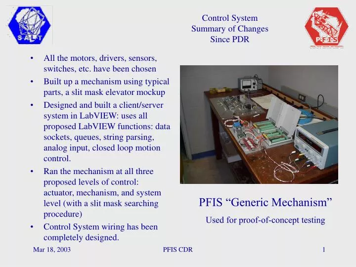
Control SystemSummary of Changes Since PDR • All the motors, drivers, sensors, switches, etc. have been chosen • Built up a mechanism using typical parts, a slit mask elevator mockup • Designed and built a client/server system in LabVIEW: uses all proposed LabVIEW functions: data sockets, queues, string parsing, analog input, closed loop motion control. • Ran the mechanism at all three proposed levels of control: actuator, mechanism, and system level (with a slit mask searching procedure) • Control System wiring has been completely designed. PFIS “Generic Mechanism” Used for proof-of-concept testing PFIS CDR
Control SystemHardware Block Diagram • Control fiber to payload • AC & RS232 from payload back to top hex, for Etalon controllers • 3 PFIS cooled electronics boxes inside PFIS structure • Main (Chassis, power supplies) • Box 1 (Slit mask, wave plate, shutter, focus) • Box 2 (Beam splitter, Grating, Filter, Articulation) PFIS CDR
Control SystemPower Management and Distribution • SALT Isolator switch provides power to all of PFIS • Within PFIS, PXI & sensors can be powered without power to actuators • Motors and pneumatics are each powered separately • Etalon High Voltage is interlocked with sensors near HV connectors. PFIS CDR
Control SystemStatus of Electrical Design • All components have been identified and assigned locations: • Main box with PXI chassis, power supplies, digital & analog inputs • Satellite box 1: slit mask, wave plate, focus, and shutter • Satellite box 2: grating, filter, articulation, and beam splitter • Wiring diagrams & interlock logic are complete - ready to buy & build • Each satellite box implements its interlocks with a Programmable Logic Device • All end-of-travel conditions are sensed • We use a “fail asserted” approach: a broken wire looks like a hard limit • Each hardware interlock is backed up by a matching software interlock • The low-level software interlocks are avoided by the configuration state machine • Shutter interface with SAAO detector subsystem is final PFIS CDR
Control SystemHeat Budget • Steady-state heat is all in cooled boxes; 400 W is well below PFIS allocation of 1.3 kW • Primary source of uncooled heat is motors • Most motors have very low duty cycle, and are not used during observing; time-averaged power is about 1 W • Exceptions are polarimetric modes - in the high-speed shuffle modes, duty cycle can be very high. For a 25% duty cycle, add 0.8 W for linear and another 0.8 W for circular. PFIS CDR
Control SystemMotors and Drivers • 8 axes of motion control • 2 NI 7334 cards (1 spare) • 4 Oriental Motors (with drivers) • 2 embedded (OEM) motors • 1Slo-syn high torque motor for articulation • 1 DC stepper mike for focus PFIS CDR
Control SystemSoftware Block Diagram • Client/server design • Client sends text strings • Server runs mechanisms • 3 levels of server software: • actuator level • mechanism level • procedure level • Interlocks are built in at all levels PFIS CDR
Control SystemSoftware State Diagram • Operational complexity has been tamed • Maximum time to reconfigure: spectroscopy to Fabry-Perot Imaging. • This is driven by two mutually exclusive operations • Other operations can be done in parallel PFIS CDR
Control SystemSoftware Development Plan • All LabVIEW: no custom C code needed • Top-down design • Create LabVIEW type-def data base (data clusters & enumerated commands) • Get astronomer and operator feedback on GUI pages & navigation • Rapidly prototype & use GUI • Bottom-up implementation • Code & debug actuator wrappers • Integrate & test actuator wrappers at mechanism level • Assemble mechanism VIs into operational procedures • Document each VI as we go • Use LabVIEW documentation process • Place text boxes on diagram • Configuration management: use LabVIEW version control PFIS CDR
Control SystemSoftware Integration & Test Plan • Match LabVIEW coding sequence to mechanism fabrication • LabVIEW modules are ready as mechanism comes on line • Bench testing of mechanism & control software happen together • Develop mechanism acceptance test procedures during mechanism I&T • Debugged mechanism software modules get used in high level observing procedures • High-level procedures will include short- and long-form test procedures PFIS CDR
Control SystemState Transition Table • Table-driven state machine provides 3rd level of interlocks, in addition to hardware interlocks & actuator-level software interlocks • Table prevents PFIS from being driven into a bad state • “State detection” is part of startup & error recovery - figures out what state PFIS is in PFIS CDR