Download
1 / 59
590 likes | 838 Views
Discussion of Burnthrough Test Method for Aircraft Thermal Acoustic Insulation Blankets. Tim Marker. FAA Technical Center. Standardization of Burnthrough Test. Objective: Lab-to-lab correlation of test results! . Methodology (1): Ensure proper equipment set-up using standardized tools

E N D
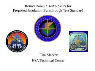
Discussion of Burnthrough Test Method for Aircraft Thermal Acoustic Insulation Blankets Tim Marker FAA Technical Center
Standardization of Burnthrough Test Objective: Lab-to-lab correlation of test results! Methodology (1): Ensure proper equipment set-up using standardized tools to allow quick and accurate measurement of critical dimensions and settings. Methodology (2): Ensure proper calibration and test techniques by visiting labs and witnessing actual calibration and burnthrough tests. Methodology (3): Prepare and test identical samples (i.e., RR VI)
Special Thanks to: Scott Anacker Steve Morgan For the development of the burner adjustment tools
Methodology (1): Ensure proper equipment set-up using standardized tools to allow quick and accurate measurement of critical dimensions and settings.
Initial Burner Adjustments, General Set-up Check: 1. Proper Components (H215 stator, F-124 turbulator, PL fuel nozzle, etc) 2. Test Frame Level 3. 30o Angle for Cone Face, Test Frame, T/C Rake, Calorimeter 4. All Flanges Sealed Measure: 1. Burner Cone Protrusion 2. Nozzle Depth 3. Stator Depth 4. Ignitor Depth
Adjusting Cone Rotation by Measuring Vertical Distance to Centerline Angle attached to faceplate
Adjusting Frame Position to Ensure Perpendicular to Cone Centerline
Differences in Turbulator Position Burnthrough Test Seat Test
Methodology (2): Ensure proper calibration and test techniques by visiting labs and witnessing actual calibration and burnthrough tests.
Lab 1 Igniter flange not sealed Fuel rail too short, preventing proper nozzle depth Thermocouple rake and calorimeter rake not properly oriented, resulting in burner cone at obscure angle when performing calibration Poor burner mounting, producing instability Center of test frame not aligned with center of burner cone Test frame formers reversed Direct visual observation of blankets not possible
Lab 2 Rear faceplate not sealed Shutter-style air damper installed on end of intake hose; OEM damper removed Top of center vertical former cut on angle, not square Lab overall very organized
Lab 3 Incorrect fuel nozzle (previous to inspection) Incorrect blower fan (previous to inspection) Incorrect internal stator Incorrect warm-up/calibration procedure (must be 2 individual events) Igniter flange not sealed Direct visual observation of blankets not possible Excessively long igniter wires, wrapped around fuel rail Overall lab very organized, equipment in excellent condition
Lab 4 Poor burner mounting, producing instability Incorrect location of test stand, calorimeter, and thermocouple rake with reference to burner No detents on rotation mechanism; proper position with regard to test frame, thermocouples, and calorimeter not possible Loose thermocouple mounting bracket; impossible to properly set thermocouple location Test frame welded together, not bolted, resulting in severe warpage Incorrect fuel nozzle Incorrect fuel flowrate
Lab 4 (con’t) Calorimeter face carbon build-up, resulting in incorrect readings Test chamber crosswind Incorrect warm-up/calibration procedure (must be 2 individual events) Backface calorimeters not perpendicular to test frame Intake hose coiled up, possibly affecting accuracy of intake air measurement Direct visual observation of blankets not possible No fuel filter
FAA Lab Incorrect location of test stand, calorimeter, and thermocouple rake with reference to burner
FAA Lab Distance measured from frame center
FAA Lab Distance measured from frame center