Download
1 / 28
290 likes | 518 Views
Chapter 3 Resistive Circuits. Adjustable Voltage Source. Figure 3.1-1 The circuit being designed provides an adjustable voltage, v, to the load circuit. Figure 3.1-2 (a) A proposed circuit for producing the variable voltage v (b) the equivalent circuit after the potentiometer is modeled.

E N D
Adjustable Voltage Source Figure 3.1-1The circuit being designed provides an adjustable voltage, v, to the load circuit. Figure 3.1-2(a) A proposed circuit for producing the variable voltage v(b) the equivalent circuit after the potentiometer is modeled
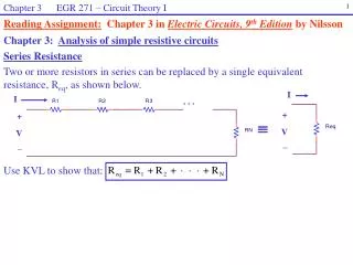
Kirchhoff’s Law Figure 3.3-1(a) An electric circuit. (b) The same circuit, redrawn using straight lines and horizontal and vertical elements. (c) The circuit after labeling the nodes and elements. Example 3.3-1 Figure 3.3-2 Four circuit drawings.
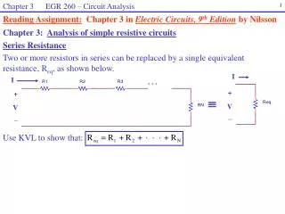
Kirchhoff’s Law Kirchhoff’s Current Law (KCL)The algebraic sum of the currents into a node at any instant is zero Kirchhoff’s Voltage Law (KVL)The algebraic sum of the voltages around any loop in a circuit is identically zero for all time
Kirchhoff’s Law Figure 3.3-4 (a) The circuit considered in Example 3.3.2 and (b) the circuit redrawn to emphasize the nodes. Example 3.3-2 Example 3.3-3 Figure 3.3-5Circuit with two constant-voltage sources.
Kirchhoff’s Law Figure 3.3-6(a)Circuit with dependent source and an ammeter(b)Equivalent circuit after replacing the ammeter by a short circuit Example 3.3-4 Figure 3.3-7The circuit of Figure 3.3-10 after labeling the nodes and some element currents and voltages.
Kirchhoff’s Law Figure 3.3-8(a)Circuit with dependent source and a voltmeter(b)Equivalent circuit after replacing the voltmeter by a open circuit. Example 3.3-5 Figure 3.3-9The circuit of Figure 3.3-12b after labeling the nodes and some element currents and voltages.
Kirchhoff’s Law Exercise 3.3-1 Exercise 3.3-2 Exercise 3.3-3 Exercise 3.3-4
A Single Loop Circuit – Voltage Divider Figure 3.4-1Single loop circuit with a voltage source vs. - KCL - KVL
A Single Loop Circuit – Voltage Divider Figure 3.4-2Voltage divider circuit with R1=9Ω Example 3.4-1 Figure 3.4-3Equivalent circuit for a series connection of resistors.
A Single Loop Circuit – Voltage Divider Figure 3.4-4(a) A circuit containing series resistors(b) The circuit after the ideal ammeter has been replaced by the equivalent short circuit and a label has been added to indicate the current measured by the ammeter, im. Example 3.4-2
A Single Loop Circuit – Voltage Divider Exercise 3.4-2 Exercise 3.4-1 Exercise 3.4-3 Exercise 3.4-4
Parallel Resistors and Current Division Figure 3.5-1A circuit with a current wource. Figure 3.5-2 Parallel circuit with a current source. Figure 3.5-3Equivalent circuit for a parallel circuit.
Parallel Resistors and Current Division Figure 3.5-4Set of N parallel conductances with a current source is.
Parallel Resistors and Current Division Figure 3.5-7(a) A circuit containing parallel resistors(b) The circuit after the ideal voltmeter has been replaced by the equivalent open circuit and a label has been added to indicated the voltage measured by the voltmeter, vm.(c) The circuit after the parallel resistors have been replaced by an equivalent resistance. Example 3.5-1 Example 3.5-2
Parallel Resistors and Current Division Figure E3.5-2(a) A current divider. (b) The current divider after the ideal ammeter has been replaced by the equivalent short circuit and a label has been added to indicate the current measured by the ammeter im. Exercise 3.5-1 Exercise 3.5-2
Serious Voltage Source and Parallel Current Source Figure 3.6-1(a) A circuit containing voltage sources connected in series(b) an equivalent circuit. Figure 3.6-2(a) A circuit containing parallel current sources(b) an equivalent circuit.
Serious Voltage Source and Parallel Current Source Table 3.6-1Parallel and Series Voltage and Current Sources.
Circuit Analysis Figure 3.7-1Circuit with a set of series resistors and a set of parallel resistors. Figure 3.7-2 Equivalent circuit of Figure 3.7-1.
Circuit Analysis Figure 3.7-3(a) Circuit for Example 3.7-1. (b) Partially reduced circuit. Example 3.7-1 Figure 3.7-4 Equivalent circuit.
Circuit Analysis Figure 3.7-5. Example 3.7-2
Circuit Analysis Figure 3.7-6The equivalent resistance looking into terminals c-d is denoted as Reqc-d .
Circuit Analysis Exercise 3.7-1 Exercise 3.7-2 Exercise 3.7-3
Circuit Analysis using MATLAB Figure 3.8-1 (a) A resistive circuit and (b) an equivalent circuit. Figure 3.8-2 Plot of I versus Vs for the circuit shown in Figure 3.8-1.
Circuit Analysis using Mathcad Figure 3.9-1 (a) An example circuit and (b) computer analysis using Mathcad.
Adjustable Voltage Source Figure 3.10-1 The circuit being designed provides an adjustable voltage, v, to the load circuit. Figure 3.10-2 (a) A proposed circuit for producing the variable voltage, v, and (b) the equivalent circuit after the potentiometer is modeled. Figure 3.10-3 The circuit after setting R1=R2=R.
Equivalent Circuits Table 3.12-1Equivalent Circuits for Series and Parallel Elements.
Homework #2 Problems 3.3 – 2, 4, 7, 9 3.4 – 2, 4, 6 3.5 – 2, 4, 6 3.7 – 2, 4, 6, 10, 14