Download
1 / 50
730 likes | 1.96k Views
Space Radiation Effects in Electronic Components. Len Adams Professor Associate, Brunel Univ. Consultant to Spur Electron. For: PA and Safety Office. May 2003 . Space Radiation Effects in Electronic Components Structure of Presentation.

E N D
Space Radiation Effectsin Electronic Components. Len Adams Professor Associate, Brunel Univ. Consultant to Spur Electron. For: PA and Safety Office. May 2003
Space Radiation Effects in Electronic ComponentsStructure of Presentation • Space radiation environment • Radiation effects in electronic components. • Radiation testing • Use of commercial components • Guide to comrad-uk resource • Open discussion
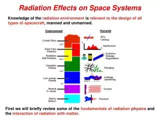
Space Radiation EnvironmentOverview • Complex and Dynamic • Trapped Radiation – ‘Belts’ of energetic electrons and protons • Cosmic Rays (Energetic Ions) • Solar Event protons
Space Radiation EnvironmentTrapped Radiation • Electrons and Protons are trapped in the Earths magnetic field, forming the ‘Van Allen’ belts. • Electrons up to 7 MeV • Protons up to a few hundred MeV.
Space Radiation EnvironmentTransiting Radiation • Very high energy Galactic Cosmic Rays originating from outside the solar system • Solar Events. (X-rays, protons and heavy ions)
Space Radiation EnvironmentGalactic Cosmic Rays • 85% Protons, 14% Alpha particles, 1% Heavy Nuclei. • Energies up to GeV • Expressed in terms of Linear Energy Transfer (LET) for radiation effects purposes
Space Radiation EnvironmentSolar Flares • Occur mostly near first and last year of solar maximum • Solar Events, composed mainly of protons with minor constituent of alpha particles, heavy ions and electrons
Space Radiation EnvironmentSouth Atlantic Anomaly • Distortion of the earth’s magnetic field allows the proton belts to extend to very low altitudes in the region of South America • Low Earth Orbiting satellites will be exposed to high energy protons in this region
Radiation Effects in Components(1) IONIZATION Mechanism : Charge generation, trapping and build-up in insulating layers. Due to: Electrons, Protons. Main Effects: Parameter drift. Increased leakage currents. Loss of noise immunity. Eventual functional failure
Radiation Effects in Components(2) DISPLACEMENT DAMAGE Mechanism: Disruption of crystal lattice Due to: Protons Main Effects: Reduced gain, increased ‘ON’ resistance, reduced LED output, reduced charge transfer efficiency in CCDs.
Radiation Effects in Components(3) SINGLE EVENT Mechanism: Dense path of localised ionization from a single particle ‘hit’ Due to: Cosmic rays, high energy protons. Main Effects: Transient current pulses, variety of transient and permanent ‘Single Event Effects’
Radiation Effects in Components(4) Single Event Effects in detail Latch-up. Permanent, potentially destructive Bit flips (‘Single Event Upset’) in bistables High Anomalous Current (HAC), ‘snap-back’ Heavy Ion Induced Burn-out in power MOS Single Event Gate Rupture (SEGR) Single Event Transient, noise pulses, false outputs ‘Soft Latch’ (device or system ‘lock up’)
Typical Single Event Transient Requirements. • Output voltage swing of rail voltage to ground and ground to rail voltage. • Duration: 15 microseconds for Op-Amps. 10 microseconds for comparators, voltage regulators and voltage references. 100 nanoseconds for opto-couplers.
Radiation TestingSpecifications and Standards • Total Ionizing Dose: SCC-22900 (ESA-SCC) Mil Std 883E Method 1019.6 (DESC) ASTM F1892 (includes ELDRS) • Single Event: SCC-29500 (ESA-SCC) EIA/JEDEC Standard EIA/JESD57 ASTM F1192
Radiation TestingImportant Considerations • Choice of radiation source. • Specifications and Standards • Worst case or application bias • Test software • Number of samples • Traceability • Databasing
Radiation TestingChoice of Source Total Ionizing Dose: Co-60 gamma or 1-3 MeV electrons (Linac or VdG) Displacement Damage: Protons (10-20 MeV), Neutrons (1 MeV), Electrons (3-5 MeV) Single Event: Heavy Ion Accelerator (ESA-Louvain HIF), Proton Accelerator (ESA-PSI PIF) Cf-252 ‘CASE’ laboratory system.
Technologies generally considered to be radiation tolerant (~ 300 krad) • Diodes (other than zener). • TTL logic (e.g. 54xx series). • ECL (Emitter Coupled Logic). • GaAs (Gallium Arsenide) technologies. • Microwave devices. • Crystals. • Most passives.
Radiation TestingSample Size/Traceability Sample Size: Total Ionizing Dose. Minimum 5 samples. 4 test, 1 reference. Single Event. 3 samples recommended. Traceability: Use single Lot-Date-Code for test and flight hardware.
Dose-rates for testing. - High Dose Rate: SCC 22900 Window 1. 1-10 rads/sec. MIL883E 1019.6. 50-300 rads/sec. • Low Dose Rate: SCC 22900 Window 2. 0.01-0.1 rads/sec. MIL883E 1019.6. 0.01 rads/sec. Elevated Temp. 0.5-5 rads/sec.
Radiation TestingTest Software (Single Event) • Test pattern dependence. All 1, All 0, Alternate 1-0, Chequerboard, MOVI. • Different sensitivities for different registers. • Dead Time. (detect flip/record/rewrite) • How to test Processors (‘Golden Chip’ ?) • Possibility to run application software ? Beware of software/hardware interaction.
Radiation TestingAnd finally…… TEST IT LIKE YOU FLY IT FLY IT LIKE YOU TEST IT (Ken LaBel. GSFC)
Use of Commercial Components • The use of commercial technology does NOT necessarily result in cost-saving. • Cost of Ownership is the important consideration. • First choice should always be QML or Space Quality components if available.
Why Use Commercial Technology ? • Complexity of functions • Performance • Availability (limited number of QML/Space suppliers).
What are the drawbacks of commercial technology? • Little or no traceability • Rapid and unannounced design and process changes. • Rapid obsolescence • Packaging Issues (Plastic). - Effect of burn-in on radiation response - Deep dielectric charging in space (?)
COTS Hardness Assurance • Define the hazard • Evaluate the hazard • Define requirements • Evaluate device usage • Discuss with designers • Iterate process as necessary
Risk Assessment & Mitigation • Components list review by a radiation expert • Good Radiation Design Margin (2-5) • Fully characterise key components • Limit the use of new technologies • Eliminate or shield marginal technologies • Maintain awareness of developments in radiation effects • Do not cut back on testing • Look for system solutions
Countermeasures/MitigationTotal Ionizing Dose. • Additional shielding. Only effective in electron dominated environments. • Cold redundancy (‘sparing’). Not effective for all technologies. • Generous derating. • Robust electronic design. High drive currents, low fan-out or loading. Large gain margins, high noise immunity etc.
Countermeasures/Mitigation. Single Event Effects • Note that additional shielding is NOT effective. • Ensure systems are not sensitive to transient effects. • Use fault tolerant design techniques. • Use Error Detection and Correction for critical circuits. • Ensure systems can re-boot autonomously.
COMRAD-UKAn integrated Web resource of components radiation effects data.
Why Integrated Web Resource ? • COMRAD provides more than a database. it includes : Components radiation effects database. A tutorial handbook. Links to radiation effects sites. Links to manufacturers sites. Links to publications in .pdf format. ‘Experts Forum’ for technical discussions.
Origins of COMRAD-UK Database • ESA RADFX (on discs) • Database Round Table (RADECS 1993) • Discussions with Space Agencies, Scientific Institutes and Industry • Discussions with CERN LHC Project and Detector groups.
Aims of COMRAD-UK Database • To be ‘informative’ not ‘regulatory’. • To contain recent data and be continuously updated. • To provide data summary and detailed tabulated data (if available). • To provide contact details for the test authority. • To be expandable for High-Energy Physics and Avionics
COMRAD-UK Database status. • 700 Total Dose records • 280 Single Event Records • Being updated on a monthly basis • Primary data resources: IEEE NSREC Data Workshop and Proceedings RADECS Data Workshop and Proceedings ESA Contract Reports. IEEE Publications. CERN reports and publications
Origins of COMRAD-UK Handbook • ESA Radiation Design Handbook. PSS-609 • Handbook of Radiation Effects. OUP 1993. • The use of commercial components in aerospace technology. BNSC Contract Report 1999. • Participation in CERN RD-49 collaboration. ‘Hardened microelectronics and commercial components’. • Various international seminars and workshops over past 5 years.
Aims of COMRAD-UK Handbook • A brief (100 page) tutorial guide to the space application of components. • To assist in the assessment of components in the COMRAD database for any particular mission. • Provides guidance on Hardness Assurance practices. • Discusses the application of commercial components.
Handbook Contents • The Space Radiation Environment • Radiation Effects Prediction Techniques • Radiation Effects in Electronic Components • Designing Tolerant Systems • Radiation Effects Databases • Radiation Testing • Hardness Assurance Management • Recommended Procurement Practices
COMRAD-UKExperts Forum The Experts Forum allows users to post queries on the Web-site. These will, as far as possible, be answered by Spur Electron but it is also possible for other users to provide an input and start a discussion.
Summary • COMRAD-UK is a Web based integrated source of components radiation effects data. • COMRAD-UK is co-sponsored by the British National Space Centre and maintained on their behalf by SPUR-Electron. • The site is under continuous development • - comments and suggestions are welcome. • comrad-uk.net • radinfo@spurelectron.com
Hardness Assurance in the real world WE HAVEN’T GOT THE MONEY SO WE’VE GOT TO THINK. (Lord Rutherford 1871-1937)