Download
1 / 21
210 likes | 425 Views
Design and Implementation of BSC Software in a WLL System. A case study on designing and implementing communication software. Introduction. Wireless Local Loop

E N D
Design and Implementation of BSC Software in a WLL System A case study on designing and implementing communication software
Introduction • Wireless Local Loop • Local Loop (or Access Network) is a system that connects subscribers to the public switched telephone network (PSTN). In some cases, it is referred to as "the last mile" in a telephone network. • WLL system use radio signals as a substitute for copper for all or part of the connection between the subscriber and the switch. • It’s also called radio in the loop (RITL), fixed-radio access (FRA), or fixed wireless access (FWA).
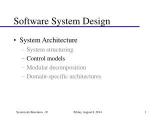
WLL System Structure Local Telephone Switch BSC BS RSU BS: Base Station RSU: Remote Subscriber Unit BSC: Base Station Controller Wireless Local Loop System Structure
WLL System Interface TMN-MS Q3 Q3 1 2 UNI SNI PSTN Terminal RSU BS BSC Switch WLL System UNI: User Network Interface SNI: Service Node Interface, A Interface TMN-MS: Telecommunication Management Network Management Service 1: Abis Interface 2: Air Interface
Advantages of WLL Technology • Faster deployment • Lower construction costs • Lower network maintenance, management, and operating costs • Lower network extension costs
WLL Products RSU BSC
RSU RSU RSU RSU RSU RSU BS BS BS WLL System Deployment 100 Abis Interface HDLC A Interface SS7,CSS1 PBX Switch 100 BSC RS-232 OAMC 100 OAMC: Operation, Administration and Maintenance Center Air Interface CDMA
BSC Software System Call System Interrupt Admin. Signaling Timing Call Call OAMC Process M2ST: Message to Signal Transformation CSS1: China Signaling System 1 SS7: Signaling System 7 Database Mgmt Ticking Timing Mgmt Task Scheduler M2ST M2ST M2ST M2ST SS7 CSS1 HDLC RS-232 Switch HDLC Driver RS-232 Driver SS7 Driver CSS1 Driver Driver
BSC Software Requirements • Real Time • Multiple Tasks • Event Driven System • Reliability • Compact • Extensibility and Reusability
BSC Software Design Tools • FSM or Extended FSM • A Finite State Machine is a kind of state machine that has a limited or finite number of possible states. • M = (I,O,S,D,L). • D: ISS • L: ISO • Can be used to describe the behavior of every component or task. • FSM can be minimized or optimized.
BSC Software Design Tools • SDL (ITU-T Recommend) • SDL (Specification and Description Language) is an object-oriented, formal, and graphical language. It is intended for the description of complex, event-driven, real-time, and communicating systems. • Some software, such as SDT, can translate SDL system into an executable application without manual coding.
BSC Software Design Tools • MSC (ITU-T Z.120 ) • Message Sequence Chart is a trace language which in its graphical form admits a particularly intuitive representation of system runs in distributed systems while focusing on the message interchange between communicating entities and their environment. • The latest ITU-T standard syntax of MSC can be used to support early phases of the software development cycle.
Call Call Process Process CSS1 Module Design Digital Channel Module MFC Module M2ST Digital Channel Driver CSS1 MFC Driver CSS1 Driver Call Process: Call initialization, hold, release and signal transformation MFC Module: Multi Frequency Control signal transformation MFC Driver: Decouple MFC Module from hardware Digital Channel Module: Digital Channel signal transformation Digital Channel Driver: Decouple Digital Channel Module from hardware
FST Caller Connection Initialization BSC RSU SW Digital Channel MFC BS Sync. Check Verification User ID User ID Channel Allocation Dialing Tone Dialing Tone DTMF Check Callee Number . Callee Number . . . . . Callee Number Callee Number Channel Allocation Allocation Verification Channel Allocation Verification MFC Allocation MFC Verification Callee Number Callee Number Callee Number Callee Number Ask Callee Number Callee Number Callee Number Callee Number A 3 KD KB(Idle ) Callee Info MFC Idle Callee Number Stop DTMF Check [Ringing] [Ringing] [Ringing] [Ringing] Callee Answer Callee Answer Talking Talking Talking BSC RSU SW Digital Channel MFC BS FST: Fixed Subscriber Terminal SW: Switch Caller Pick up the phone BSC MSC Callee Pick up the phone
FST Callee Connection Initialization BSC RSU SW Digital Channel MFC BS Allocation Channel Allocation Verification Verification MFC Allocation Verification Callee Number A1 . . . Callee Number Extension Number A3 Callee Info KD Call Type KB MFC IDLE Call User Find User Sync. Check Verification User ID Call User Verification Allocate Channel Allocate Channel Allocate Channel Callee Answer Callee Answer Talking Talking Talking Talking SW Digital Channel MFC BSC BS RSU [Ring] Callee pick up phone
MFC Module FSM E: Event from MFC Driver M: Message from other tasks
IDLE M Allocation Allocation E M Release N C IDLE? M Release Allocation Y N IDLE? C Allocation Fail M T1'=300ms Y BUSY IDLE T1=300ms Allocation IDLE IDLE IDLE Allocation Block Block Release M E E Block C Block IDLE M M IDLE IDLE IDLE Digital Channel Model SDL
CSS1 Module Implementation • Development Tools • Motorola 68000 series (MCC68K, LNK68K, ASM68K); • Multi task simulation • Motorola 68302 (EDX) Event Driven eXecution system • Test Tool • Motorola XRAY68K debugger
User Interface Data ResponseMsg() Windows Msg SendMsg() Dispatcher ResponseMsg() Windows Msg SendMsg() pc_send_message() BSC RS-232 pc_recv_message() WriteFile() OAMC OAMC Module Design