Download
1 / 18
210 likes | 783 Views
MESB374 System Modeling and Analysis Transfer Function Analysis. Transfer Function Analysis. Dynamic Response of Linear Time-Invariant (LTI) Systems Free (or Natural) Responses Forced Responses Transfer Function for Forced Response Analysis Poles Zeros General Form of Free Response

E N D
MESB374 System Modeling and AnalysisTransfer Function Analysis
Transfer Function Analysis • Dynamic Response of Linear Time-Invariant (LTI) Systems • Free (or Natural) Responses • Forced Responses • Transfer Function for Forced Response Analysis • Poles • Zeros • General Form of Free Response • Effect of Pole Locations • Effect of Initial Conditions (ICs) • Obtain I/O Model based on Transfer Function Concept
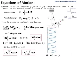
Time constant Dynamic Responses of LTI Systems Ex:Let’s look at a stable first order system: • Take LT of the I/O model and remember to keep tracks of the ICs: • Rearrange terms s.t. the output Y(s) terms are on one side and the input U(s) and IC terms are on the other: • Solve for the output: Free Response Forced Response
Free & Forced Responses • Free Response (u(t) = 0 & nonzero ICs) • The response of a system to zero input and nonzero initial conditions. • Can be obtained by • Let u(t) = 0 and use LT and ILT to solve for the free response. • Forced Response (zero ICs & nonzero u(t)) • The response of a system to nonzero input and zero initial conditions. • Can be obtained by • Assume zero ICs and use LT and ILT to solve for the forced response (replace differentiation with s in the I/O ODE model).
In Class Exercise Find the free and forced responses of the car suspension system without tire model: • Take LT of the I/O model and remember to keep tracks of the ICs: • Rearrange terms s.t. the output Y(s) terms are on one side and the input U(s) and IC terms are on the other: • Solve for the output: Free Response Forced Response
Forced Response & Transfer Function Given a general n-th order system model: The forced response(zero ICs) of the system due to input u(t) is: • Taking the LT of the ODE: Forced Response Transfer Function Inputs = Inputs = Transfer Function
Static gain Transfer Function Given a general nth order system: The transfer function of the system is: • The transfer function can be interpreted as: u(t) Input y(t) Output U(s) Input Y(s) Output Differential Equation G(s) Time Domain s - Domain
Transfer Function Matrix For Multiple-Input-Multiple-Output (MIMO) System with m inputs and p outputs: Inputs Outputs
Poles The roots of the denominator of the TF, i.e. the roots of the characteristic equation. • Zeros • The roots of the numerator of the TF. m zeros of TF Poles and Zeros Given a transfer function (TF) of a system: n poles of TF
(2) For car suspension system: Find TF and poles/zeros of the system. (1) Recall the first order system: Find TF and poles/zeros of the system. Examples Pole: Pole: Zero: Zero: No Zero
+ + Output Input System Connections Cascaded System Output Input Parallel System Feedback System + - Output Input
General Form of Free Response Given a general nth order system model: The free response (zero input) of the system due to ICs is: • Taking the LT of the model with zero input (i.e., ) A Polynominal of s that depends on ICs Free Response (Natural Response) = Same Denominator as TF G(s)
Free Response (Examples) Ex: Find the free response of the car suspension system without tire model (slinker toy): Ex: Perform partial fraction expansion (PFE) of the above free response when: (what does this set of ICs means physically)? phase: initial conditions Decaying rate: damping, mass Frequency: damping, spring, mass Q: Is the solution consistent with your physical intuition?
Img. Real Free Response and Pole Locations The free response of a system can be represented by: exponential decrease constant exponential increase decaying oscillation Oscillation with constant magnitude increasing oscillation t
Complete Response Y(s) Output U(s) Input • Complete Response Q: Which part of the system affects both the free and forced response ? Q: When will free response converges to zero for all non-zero I.C.s ? Denominator D(s) All the poles have negative real parts.
Obtaining I/O Model Using TF Concept(Laplace Transformation Method) • Noting the one-one correspondence between the transfer function and the I/O model of a system, one idea to obtain I/O model is to: • Use LT to transform all time-domain differential equations into s-domain algebraic equations assuming zero ICs(why?) • Solve for output in terms of inputs in s-domain to obtain TFs (algebraic manipulations) • Write down the I/O model based on the TFs obtained
Example – Car Suspension System x p • Step 1: LT of differential equations assuming zero ICs • Step 2: Solve for output using algebraic elimination method • # of unknown variables = # equations ? 2. Eliminate intermediate variables one by one. To eliminate one intermediate variable, solve for the variable from one of the equations and substitute it into ALL the rest of equations; make sure that the variable is completely eliminated from the remaining equations
Example (Cont.) from first equation Substitute it into the second equation • Step 3: write down I/O model from TFs