Download
1 / 57
570 likes | 588 Views
Dive into the world of TinyOS, an OS designed for tiny networked sensors. Explore disaster management, habitat monitoring, and the characteristics of network sensors. Understand the TinyOS outline, hardware components such as Isun motherboard and expansion connector, and sensor boards' functionalities. Learn about the energy efficiency and power breakdown of TinyOS, making it an ideal system for tiny devices.

E N D
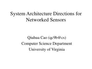
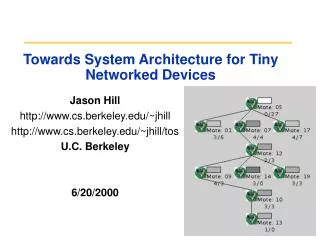
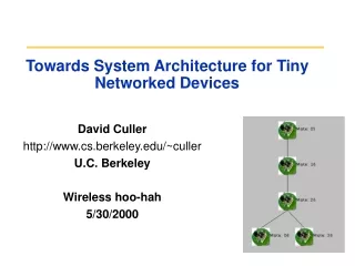
Operating System Design for Tiny Networked Sensors David Culler Computer Science Division U.C. Berkeley www.cs.berkeley.edu/~culler
Low-power Wireless Communication I SD Q SD baseband PLL filters mixer LNA Emerging Microscopic Devices • CMOS “stuff” is not just Moore’s law • Micro Electical Mechanical Systems (MEMS) • rich array of sensors are becoming cheap and tiny • Imagine, all sorts of chips that are connected to the physical world and to cyberspace! TinyOS with Pister
Circulatory Net What can you do with them? Disaster Management • Embed many distributed devices to monitor and interact with physical world • Network these devices so that they can coordinate to perform higher-level tasks. => Requires robust distributed systems of hundreds or thousands of devices. Habitat Monitoring TinyOS
sensors actuators storage network Characteristics of Network Sensors • Small physical size and low power consumption • Concurrency-intensive operation • multiple flows, not wait-command-respond • Limited Physical Parallelism and Controller Hierarchy • primitive direct-to-device interface • Asynchronous and synchronous devices • Diversity in Design and Usage • application specific, not general purpose • huge device variation => efficient modularity => migration across HW/SW boundary • Robust Operation • numerous, unattended, critical => narrow interfaces TinyOS
Outline • Motivation for exploring a Tiny OS • Tiny wireless sensor experimental platform • Basics of TinyOS with Demo • Dig deeper into execution model • Emerging layers of abstraction • Directions for exploration • Wrap-up TinyOS
Isun Motherboard: Processor Core • Atmel AVR • Clock speed: 4 MHz • Memory • 8 Kbytes of program memory (flash) • 512 bytes of data RAM • 512 bytes of EEPROM on chip (write: 4 ms/byte) • 32 8 bit registers • IO capabilities • 32 general purpose IO lines • Some lines also serve more specialized purposes, e.g. UART • 10-bit 8-channel ADC • Connector interface means that the IO lines serve a more specific purposes • Interrupts • No interrupt queuing TinyOS
Radio Circuit • RFM Monolithics TR1000 916 MHz radio • On/off keying at 10 kbps (max. 19.2 kbps) • Capable of 115 kbps using amplitude shift keying • Capable of turning on in 30 us • Low-power listening by switching on and off on a sub-bit granularity • Processor interface • RFM CNTRL 0 and 1 – switch between transmit, receive, and sleep • Raw, unbuffered access to transmit (RFM TX) and receive (RFM RX) • Requires DC balanced signal – an equal number of 1’s and 0’s in the signal • Sampling on reception and modulating on transmission done is software • Too much noise in received signal to use UART for sampling • too little flexibility offered by UART • Imposes real time constraints on the system • Power usage • Transmit current: 7 mA • Receive current: 4.5 mA • Sleep: 5 uA TinyOS
Expansion Connector • Documented hardware interface • Swap components on either side of the connector while preserving investment in sensors or main boards • Sensor interfaces • 4 lines dedicated to switching components on and off • 7 analog voltage sensing lines • 2 I2C busses • SPI • UART lines • Debugging aids • All radio-related signals: RX, TX, base band, control signals, signal strength • Programming interfaces • SPI and reset signals for the main processor and the coprocessor • Ground, Vcc for both analog and digital circuits • 12 lines reserved for future use TinyOS
Sensor Boards • Basic Sensor Proto • Photo resistor – PW1 and ADC1 • Thermistor – PW2 and ADC2 • Prototyping area • Vibration Sensor • Photo resistor: PW1 and ADC1 • Thermistor: PW4, ADC6 • 2 axis accelerometer: ADC2 and 3, PW2 • Digital temperature: I2C Bus 1 • 2 axis magnetometer • Convert magnetic fields into a differential output • Field range -2 to +2 gauss • Sensitivity 3.2mV/V/gauss • Resolution: 27gauss at 10Hz • Bandwidth: 5MHz TinyOS
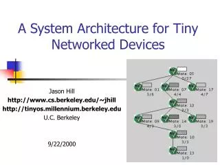
Isun Networked Sensor • 1” x 1.5” motherboard • ATMEL 4Mhz, 8bit MCU, 512 bytes RAM, 8K pgm flash • 900Mhz Radio (RF Monolithics) 10-100 ft. range • ATMEL network pgming assist • Radio Signal strength control and sensing • I2C EPROM (logging) • Base-station ready • stackable expansion connector • all ports, i2c, pwr, clock… • Several sensor boards • basic protoboard • tiny weather station (temp,light,hum,press) • vibrations (acc, temp, ...) • accelerometers • magnetometers TinyOS
Panasonic CR2354 560 mAh Basic Power Breakdown… • But what does this mean? • Lithium Battery runs for 35 hours at peak load and years at minimum load! • three orders of magnitude difference! • A one byte transmission uses the same energy as approx 11000 cycles of computation. • Idleness is not enough, sleep! TinyOS
A Operating System for Tiny Devices? • Traditional approaches • command processing loop (wait request, act, respond) • monolithic event processing • bring full thread/socket posix regime to platform • Alternative • provide framework for concurrency and modularity • never poll, never block • interleaving flows, events, energy management • allow appropriate abstractions to emerge TinyOS
TOS Approach • Stylized programming model with extensive static information • Program = graph of TOS components • TOS component = command/event interface + behavior • Rich expression of concurrency • Events propagate across many components • Tasks provide internal concurrency • Regimented storage management • Current implementation is very simple • Broad range of alternative execution mechanisms TinyOS
msg_rec(type, data) msg_send_done) Tiny OS Concepts • Scheduler + Graph of Components • constrained two-level scheduling model: threads + events • Component: • Commands, • Event Handlers • Frame (storage) • Tasks (concurrency) • Constrained Storage Model • frame per component, shared stack, no heap • Very lean multithreading • Efficient Layering Events Commands send_msg(addr, type, data) power(mode) init Messaging Component internal thread Internal State TX_packet(buf) Power(mode) TX_packet_done (success) init RX_packet_done (buffer) TinyOS
Application = Component Graph Route map router sensor appln application Active Messages Serial Packet Radio Packet packet Temp photo SW HW UART Radio byte ADC byte Example: ad hoc, multi-hop routing of photo sensor readings clocks RFM bit TinyOS
Storage Breakdown (C Code) 3450 B code 226 B data TinyOS
Components Packet reception work breakdown Percent CPU Utilization Energy (nj/Bit) AM 0.05% 0.20% 0.33 Packet 1.12% 0.51% 7.58 Radio handler 26.87% 12.16% 182.38 Radio decode thread 5.48% 2.48% 37.2 RFM 66.48% 30.08% 451.17 Radio Reception - - 1350 Idle - 54.75% - Total 100.00% 100.00% 2028.66 Empirical Breakdown of Effort • can take apart time, power, space, … • 50 cycle thread overhead, 10 cycle event overhead TinyOS
Radio Packet packet Radio byte byte RFM bit TOS Execution Model • commands request action • ack/nack at every boundary • call cmd or post task • events notify occurrence • HW intrpt at lowest level • may signal events • call cmds • post tasks • Tasks provide logical concurrency • preempted by events • Migration of HW/SW boundary data processing application comp message-event driven active message event-driven packet-pump crc event-driven byte-pump encode/decode event-driven bit-pump TinyOS
Dynamics of Events and Threads bit event => end of byte => end of packet => end of msg send thread posted to start send next message bit event filtered at byte layer radio takes clock events to detect recv TinyOS
Event-Driven Sensor Data char TOS_EVENT(SENS_OUTPUT_CLOCK_EVENT)(){ return TOS_CALL_COMMAND(SENS_GET_DATA)(); } char TOS_EVENT(SENS_DATA_READY)(int data){ TOS_CALL_COMMAND(SENS_OUTPUT_OUTPUT)((data >> 2) &0x7); return 1; } • clock event handler initiates data collection • sensor signals data ready event • data event handler calls output command • common pattern TinyOS
MAIN SENS_OUTPUT LED hardware.h CLOCK PHOTO Component Composition include modules{ MAIN; SENS_OUTPUT; INT_TO_LEDS; CLOCK; PHOTO; }; MAIN:MAIN_SUB_INIT SENS_OUTPUT:SENS_OUTPUT_INIT MAIN:MAIN_SUB_START SENS_OUTPUT:SENS_OUTPUT_START SENS_OUTPUT:SENS_OUTPUT_CLOCK_EVENT CLOCK:CLOCK_FIRE_EVENT SENS_OUTPUT:SENS_OUTPUT_SUB_CLOCK_INIT CLOCK:CLOCK_INIT SENS_OUTPUT:SENS_OUTPUT_SUB_OUTPUT_INIT INT_TO_LEDS:INT_TO_LEDS_INIT SENS_OUTPUT:SENS_OUTPUT_OUTPUT_COMPLETE INT_TO_LEDS:INT_TO_LEDS_DONE SENS_OUTPUT:SENS_OUTPUT_OUTPUT INT_TO_LEDS:INT_TO_LEDS_OUTPUT SENS_OUTPUT:SENS_DATA_INIT PHOTO:PHOTO_INIT SENS_OUTPUT:SENS_GET_DATA PHOTO:PHOTO_GET_DATA SENS_OUTPUT:SENS_DATA_READY PHOTO:PHOTO_DATA_READY INT_TO_LEDS hardware.h hardware.h TinyOS
Asynchronous Sensor Interface TOS_MODULE PHOTO; JOINTLY IMPLEMENTED_BY PHOTO; ACCEPTS{ char PHOTO_INIT(void); char PHOTO_GET_DATA(void); char PHOTO_PWR(char mode); }; SIGNALS{ char PHOTO_DATA_READY(int data); }; USES{ char SUB_ADC_INIT(void); char SUB_ADC_GET_DATA(char port); }; HANDLES{ char PHOTO_ADC_DONE(int data); }; TinyOS system/PHOTO.desc
Active Messages • Sending • Declare buffer storage in a frame • Request Transmission • Naming a handler • Handle Completion signal • Receiving • Declare a handler • Firing a handler • automatic upon arrival of corresponding message • behaves like any other event • Buffer management • strict ownership exchange • tx: done event => reuse • rx: must rtn a buffer • built-in wrapper TOS_FRAME_BEGIN(INT_TO_RFM_frame) { char pending; TOS_Msg msg; } TOS_FRAME_END(INT_TO_RFM_frame); TinyOS
access appln msg buffer cast to defined format application specific ready check build msg request transmission destination identifier get handler identifier mark busy Send Message char TOS_COMMAND(INT_TO_RFM_OUTPUT)(int val){ int_to_led_msg* message = (int_to_led_msg*)VAR(msg).data; if (!VAR(pending)) { message->val = val; if (TOS_COMMAND(INT_TO_RFM_SUB_SEND_MSG)(TOS_MSG_BCAST, AM_MSG(INT_READING), &VAR(msg))) { VAR(pending) = 1; return 1; } } return 0; } msg buffer TinyOS
Completion Event • Underlying message layer notifies all sending components of completion event • may need to resume activity after other’s completion • provides reference to sent buffer to identify action • Here event propagated as output done char TOS_EVENT(INT_TO_RFM_SUB_MSG_SEND_DONE)(TOS_MsgPtr sentBuffer){ if (VAR(pending) && sentBuffer == &VAR(data)) { VAR(pending) = 0; TOS_SIGNAL_EVENT(INT_TO_RFM_COMPLETE)(1); return 1; } return 0; } TinyOS
Handling Active Messages • Fired (via dispatch) on arrival • Gains ownership to buffer passed in msg • accessed as val.data • MUST return ownership to a buffer • If lifetime(buffer) < lifetime(handler), return incoming • otherwise, return free buffer • no free buffer => must punt operation and return incoming TOS_MsgPtr TOS_MSG_EVENT(INT_READING)(TOS_MsgPtr val){ ... return val; } TinyOS
TinyOS Execution Contexts Tasks events commands Interrupts Hardware TinyOS
Typical application use of tasks • event driven data acquisition • schedule task to do computational portion char TOS_EVENT(MAGS_DATA_EVENT)(int data){ struct adc_packet* pack = (struct adc_packet*)(VAR(msg).data); printf("data_event\n"); VAR(reading) = data; TOS_POST_TASK(FILTER_DATA); ... TinyOS mags.c
Filter Magnetometer Data Task TOS_TASK(FILTER_DATA){ int tmp; VAR(first) = VAR(first) - (VAR(first) >> 5); VAR(first) += VAR(reading); VAR(second) = VAR(second) - (VAR(second) >> 5); VAR(second) += VAR(first) >> 5; VAR(diff) = VAR(diff)-(VAR(diff) >> 5); tmp = VAR(first) - VAR(second); if(tmp < 0) tmp = -tmp; VAR(diff) += tmp; if((VAR(diff) >> 5) > 85){ TOS_CALL_COMMAND(MAGS_LEDg_on)(); VAR(led_on) = 255; } } • 128 Hz sampling rate • simple FIR filter • dynamic software tuning for centering the magnetometer signal (1208 bytes) • digital control of analog, not DSP • ADC (196 bytes) TinyOS
Tasks in low-level operation • transmit packet • send command schedules task to calculate CRC • task initiated byte-level datapump • events keep the pump flowing • receive packet • receive event schedules task to check CRC • task signals packet ready if OK • byte-level tx/rx • task scheduled to encode/decode each complete byte • must take less time that byte data transfer • i2c component • i2c bus has long suspensive operations • tasks used to create split-phase interface • events can procede during bus transactions TinyOS
Digging into Communications Stack • Building up from the RFM bit level • Bit level abstracts away radio specifics • Byte level radio component collects individual bits into bytes • Packet Level constructs packets from bytes • Messaging layer interprets packets as messages • Data pump paradigm used to connect layers Messaging Packet Level Byte Level RFM Bit Level TinyOS
RFM – RFM.comp TOS_MODULE RFM; ACCEPTS{ char RFM_INIT(void); char RFM_TX_MODE(void); char RFM_TX_BIT(char data); char RFM_RX_MODE(void); char RFM_PWR(char mode); char RFM_SET_BIT_RATE(char level); }; SIGNALS{ char RFM_TX_BIT_EVENT(void); char RFM_RX_BIT_EVENT(char data); }; • Bit level interface to the RFM radio • Abstracts away bit level timing, RFM specific control logic (TX vs. RX modes) • Signals RX and TX bit events • RFM_SET_BIT_RATE accepts 3 sampling rates… 0 = 50us (2 x bit rate) 1 = 75us (1.5 x bit rate) 2 = 100us (1x bit rate) 2x Bit rate used for detecting start symbol, bit rate 1.5 x used to transition to middle of bit transmission, 1x bit rate used to read and write data TinyOS
Data Pump Paradigm • High level components initiate transfer (COMMANDS) • Lower level components signal when more data can be handled (EVENTS) • Collection of bit events aggregated into single byte event • Collection of byte events collected into single packet event … Packet Level Byte Level RFM Bit Level TinyOS
Radio Byte Level • RADIO_BYTE.comp, FOUR_B_RADIO_BYTE.comp, SEC_DED_RADIO_BYTE.comp, SEC_DED_RADIO_BYTE_SIGNAL.comp • All have similar interfaces • Transfer individual bits to the radio • Fires off TX_READY event when it can accept another byte TOS_MODULE RADIO_BYTE; ACCEPTS{ char RADIO_BYTE_INIT(void); char RADIO_BYTE_TX_BYTES(char data); char RADIO_BYTE_PWR(char mode); }; SIGNALS{ char RADIO_BYTE_RX_BYTE_READY(char data, char error); char RADIO_BYTE_TX_BYTE_READY(char success); char RADIO_BYTE_TX_DONE(void); }; TinyOS
General Radio Byte Operation • Pipelines transmission – transmits single byte while encoding next byte • Trades 1 byte of buffering for additional latency • Separates high level latencies from low level latency requirements • Encoding Task must complete before byte transmission completes • Decode must complete before next byte arrives … Encode Task Byte 1 Byte 2 Byte 3 Byte 4 Bit transmission start Byte 1 Byte 2 Byte 3 RFM Bits TinyOS
Radio Byte FSM with Tasks (Sending) 0 tx_bit &c16 / tx_byte_rdy,tx_done tx_bytes/POST_TASK 1 2 tx_bit &~c16 tx_bit &c16 / tx_byte_rdy tx_bytes/POST_TASK 4 3 tx_bit &~c16 tx_bit &~c16 State Table 0 = idle 1 = waiting to send out first byte 2 = sending out byte, no next byte 3 = sending out byte, waiting to encode next byte 4 = sending out byte, done encoding next byte Encode Task Executed tx_bit called tx_bytes accepted TinyOS tx_byte_rdy signaled tx_done signaled
Task Scheduling • currently simple fifo scheduler • Bounded number of pending tasks • When idle, shuts down node except clock • Uses non-blocking task queue data structure TinyOS
DARPA-esq demo • UAV drops nodes along road, carries one • hot-water pipe insulation for package • Nodes self configure into linear network • Calibrate magnetometers • Each detects passing vehicle • Share filtered sensor data with 5 neighbors • Each calculates estimated direction & velocity • Share results • As plane passes by, • joins network • upload as much of missing dataset as possible from each node when in range • 7.5 KB of code! TinyOS
Working Across Levels • Encoding • Low power listening • Fair and efficient network access • Proximity detection • Security • Tiny virtual machines TinyOS
Packet Encoding / Layers • Radio requires rough DC balance • No more than three ones between zeros • Manchester encoding • 4b/6b • Bit error rate significant and increases with distance • CRC, 3-redundant • …or SECDED with DC-balanced coding • careful choice of generator matrix • 8-bits => 17-bits, no CRC Radio byte components Radio packet components TinyOS
Low-Power Listening • Costs about as much to listen as to xmit, even when nothing is received • Only way to save power is to turn radio off when there is nothing to hear. • Can turn radio on/of in about 1 bit • 30 ms on every 300 ms • Can detect transmission at cost of ~2 bit times • Small sub-msg recv sampling • Application-level synchronization rendezvous to determine when to sample sleep preamble message Xmit: Recv: b Optimal Preamble = (2/3 Sxb)1/2 Jason Hill TinyOS
Networking issues in TinyOS context • Two Problems • arbitration of access to contended radio channel • even under low duty cycle, due to correlated behavior • self-organized dynamic multihop routing • Two approaches • build it into the lower communication layers • expose to the application to solve TinyOS
Media Access Control • Hardware: single channel RF radio • Nodes contend for the same wireless channel • Traffic is highly correlated • Periodic nature of sensor networks applications • detection of common events • Collision detection mechanism is not available • Channel capacity ~25 packet/s • High amount of traffic due to • High node density • High transmission rate of each node TinyOS
Options • Application attempts to schedule communication to avoid contention • limit rate • stagger initiation time • Communication stack provides adaptation and feedback TinyOS
Busy Transmission Request Listen for Random Period Transmit Idle Factors • Application cannot tell if communication was successful without additional msgs • Radio component is listening (efficiently) by default • natural to introduce CSMA within that component • Place MAC at RADIO_BYTE level in between application layer and RFM radio component • not just backoff and retry, because listening costs • If channel is very busy, backpressure to application to slow transmission rate revealed subtle jitter bug TinyOS (16 bit LFB SR)
CSMA Evaluation Channel Utilization ~70% Throughput per node is fair TinyOS
Multihop Bandwidth Management • Should self-organize into fair, dynamic multihop net • Hidden nodes between each pair of “levels” • CSMA is not enough • P[msg-to-base] drops with each hop • Investment in packet increases with distance • need to optimize for low-power fairness! • RTS/CTS costly (power & BW) • Local rate control to approx. fairness • Priority to forwarding, adjust own data rate • Additive increase, multiplicative decrease • Listen for retransmission as ack Simulation: ½ of packets get through 4 levels out TinyOS
18 15 17 16 14 B Example: Multihop Adaptive Transmission Control Max rate: 4 samples/sec - rate = 4p Channel BW ~20 p/s - cannot expect more than 1/3 thru parent Monitor number of children (n) a(n) ~ 1/n b = ½ p’ = p + a(n) on success (echo) p’ = p * b without rate control, success drops ~½ per hop TinyOS
Proximity / Location detection • Signal strength sensing • Circuit works, falls off cleanly in good environment • Incredibly sensitive to obstructions! • Error rates a useful proximity metric • Bit errors vs. packet errors • signal strength + Kalman filter provides good position detection TinyOS
RFM Digital Pot Signal Strength inc TX Proc 50k dir sel TinyOS