Download
1 / 32
320 likes | 472 Views
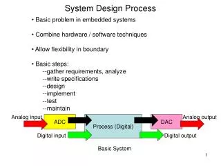
METRICS: A System Architecture for Design Process Optimization. Andrew B. Kahng and Stefanus Mantik* UCSD CSE Dept., La Jolla, CA *UCLA CS Dept., Los Angeles, CA. Motivations. How do we improve design productivity ?

E N D
METRICS:A System Architecture for Design Process Optimization Andrew B. Kahng and Stefanus Mantik* UCSD CSE Dept., La Jolla, CA *UCLA CS Dept., Los Angeles, CA
Motivations • How do we improve design productivity ? • Does our design technology / capability yield better productivity than it did last year ? • How do we formally capture best known methods, and how do we identify them in the first place ? • Does our design environment support continuous improvement of the design process ? • Does our design environment support what-if / exploratory design ? Does it have early predictors of success / failure? • Currently, there are no standards or infrastructure for measuring and recording the semiconductor design process
Purpose of METRICS • Standard infrastructure for the collection and the storage of design process information • Standard list of design metrics and process metrics • Analyses and reports that are useful for design process optimization METRICS allows: Collect, Data-Mine, Measure, Diagnose, then Improve
Related Works • OxSigen LLC (Siemens 97-99) • Enterprise- and project-level metrics (“normalized transistors”) Numetrics Management Systems DPMS • Other in-house data collection systems • e.g., TI (DAC 96 BOF) • Web-based design support • IPSymphony, WELD, VELA, etc. • E-commerce infrastructure • Toolwire, iAxess, etc. • Continuous process improvement • Data mining and visualization
Outline • Data collection process and potential benefits • METRICS system architecture • METRICS standards • Current implementation • Issues and conclusions
Potential Data Collection/Diagnoses • What happened within the tool as it ran? what was CPU/memory/solution quality? what were the key attributes of the instance? what iterations/branches were made, under what conditions? • What else was occurring in the project? spec revisions, constraint and netlist changes, … • User performs same operation repeatedly with nearly identical inputs • tool is not acting as expected • solution quality is poor, and knobs are being twiddled
Benefits • Benefits for project management • accurate resource prediction at any point in design cycle • up front estimates for people, time, technology, EDA licenses, IP re-use... • accurate project post-mortems • everything tracked - tools, flows, users, notes • no “loose”, random data left at project end • management console • web-based, status-at-a-glance of tools, designs and systems at any point in project • Benefits for tool R&D • feedback on the tool usage and parameters used • improve benchmarking
Outline • Data collection process and potential benefits • METRICS system architecture • METRICS standards • Current implementation • Issues and conclusions
Tool Tool Transmitter Java Applets wrapper Tool API Transmitter Transmitter XML Inter/Intra-net Web Server Data Mining DB Reporting Metrics Data Warehouse METRICS System Architecture
METRICS Performance • Transmitter • low CPU overhead • multi-threads / processes – non-blocking scheme • buffering – reduce number of transmissions • small memory footprint • limited buffer size • Reporting • web-based • platform and location independent • dynamic report generation • always up-to-date
donkey 2% rat 1% bull 2% 100 synthesis 20% ATPG 22% 98 postSyntTA 13% BA 8% 96 LVS % funcSim 7% hen 95% placedTA 7% 94 physical 18% LVS 5% 92 % aborted per task % aborted per machine 90 88 0 100 200 300 400 500 600 time LVS convergence Example Reports
Current Results • CPU_TIME = 12 + 0.027 NUM_CELLS (corr = 0.93) • More plots are accessible at • http://xenon.cs.ucla.edu:8080/metrics
Outline • Data collection process and potential benefits • METRICS system architecture • METRICS standards • Current implementation • Issues and conclusions
METRICS Standards • Standard metrics naming across tools • same name «same meaning, independent of tool supplier • generic metrics and tool-specific metrics • no more ad hoc, incomparable log files • Standard schema for metrics database • Standard middleware for database interface • For complete current lists see: http://vlsicad.cs.ucla.edu/GSRC/METRICS
Generic and Specific Tool Metrics Partial list of metrics now being collected in Oracle8i
Outline • Data collection process and potential benefits • METRICS system architecture • METRICS standards • Current implementation • Issues and conclusions
Capo Placer QP ECO WRoute Incr. WRoute CongestionAnalysis Testbed I: Metricized P&R Flow M E T R I C S DEF Placed DEF LEF Legal DEF Congestion Map Routed DEF Final DEF
QP CTGen QP Opt WRoute Pearl Testbed II: Metricized Cadence SLC Flow M E T R I C S DEF Placed DEF Incr. LEF GCF,TLF Clocked DEF Constraints Optimized DEF Routed DEF
Outline • Data collection process and potential benefits • METRICS system architecture • METRICS standards • Current implementation • Issues and conclusions
Conclusions • Current status • complete prototype of METRICS system with Oracle8i, Java Servlet, XML parser, and transmittal API library in C++ • METRICS wrapper for Cadence and Cadence-UCLA flows, front-end tools (Ambit BuildGates and NCSim) • easiest proof of value: via use of regression suites • Issues for METRICS constituencies to solve • security: proprietary and confidential information • standardization: flow, terminology, data management, etc. • social: “big brother”, collection of social metrics, etc. • Ongoing work with EDA, designer communities to identify tool metrics of interest • users: metrics needed for design process insight, optimization • vendors: implementation of the metrics requested, with standardized naming / semantics
Thank You http://vlsicad.cs.ucla.edu/GSRC/METRICS
Status of METRICS System • Current working METRICS systems are installed within Intel and Cadence • METRICS system works properly inside a laptop
Flow Metrics • Tool metrics alone are not enough • Design process consists of more than one tools • One tool is run multiple times • Design quality depends on the design flow and methodology (the order of the tools and the iteration within the flow) • Flow definition • Directed graph G (V,E), V T { S, F }, T { T1, T2, T3, …, Tn } (a set of tasks), S starting node, F ending node, E { Es1, E11, E12, …, Exy } (a set of edges) • Exy • x < y forward path • x = y self-loop • x > y backward path
S T1 T1 T1 T2 T2 T2 T2 T3 T3 T3 T4 T4 F Flow Example S T1 T2 T3 Optional task T4 F Task sequence: T1, T2, T1, T2, T3, T3, T3, T4, T2, T1, T2, T4
S T1 T1 T1 T2 T2 T2 T2 T3 T3 T3 T4 T4 F Flow Tracking Task sequence: T1, T2, T1, T2, T3, T3, T3, T4, T2, T1, T2, T4
... T1 T2 T3 Tn S F Multilevel FM Partitioning Experiment • Given: initial partitioning solution, CPU budget and instance perturbations (I) • Find: number of parts of incremental partitioning and number of starts • Ti = incremental multilevel FM partitioning • Self-loop multistart • n number of breakups (I = 1 + 2 + 3 + ... + n)
Multilevel FM Experiment Flow Setup foreachtestcase foreachI foreachCPUbudget foreachbreakup Icurrent = Iinitial Scurrent = Sinitial fori = 1 ton Inext = Icurrent + i run incremental multilevel FM partitioner on Inext to produce Snext ifCPUcurrent > CPUbudgetthen break Icurrent = Inext Scurrent = Snext end
Flow Results • If (27401 < num edges 34826) and (143.09 < cpu time 165.28) and (perturbation delta 0.1) then num_inc_parts = 4 and num_starts = 3 • If (27401 < num edges 34826) and (85.27 < cpu time 143.09) and (perturbation delta 0.1) then num_inc_parts = 2 and num_starts = 1 • ... Predicted CPU Time (secs) Actual CPU Time (secs)
S T1 T2 T3 T4 T5 T6 T7 T8 F Wireload Model Flow • WLM flows for finding the appropriate role of WLM • T1 = synthesis & technology mapping • T2 = load wireload model (WLM) • T3 = pre-placement optimization • T4 = placement • T5 = post-placement optimization • T6 = global routing • T7 = final routing • T8 = custom WLM generation • Post-placement and pre-placement area important steps • Choice of WLM depends on the design
Java Servlet Java Servlet Datamining Integration Inter-/Intranet DM Requests SQL Results Tables Database Datamining Interface Datamining Tool(s) Tables Tables SQL Results
Example Applications with DM • Parameter sensitivity analysis • input parameters that have the most impact on results • Field of use analysis • limits at which the tool will break • tool sweet spots at which the tool will give best results • Process monitoring • identify possible failure in the process (e.g., timing constraints are too tight, row utilization is too high, etc.) • Resource monitoring • analysis of resource demands (e.g., disk space, memory, etc.)
Predicted CPU Time (secs) Actual CPU Time (secs) DM Results: QPlace CPU Time • If (num nets 7332) then CPU time = 21.9 + 0.0019 num cells + 0.0005 num nets + 0.07 num pads - 0.0002 num fixed cells • If (num overlap layers = 0) and (num cells 71413) and (TD routing option = false) then CPU time = -15.6 + 0.0888 num nets - 0.0559 num cells - 0.0015 num fixed cells - num routing layer • ...