Download
1 / 66
700 likes | 1.05k Views
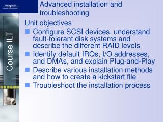
Installation and troubleshooting overview. Unit objectives. After completing this unit, you should be able to: Identify the BladeCenter components used to provide PD information List the planning elements required for the BladeCenter management network

E N D
Unit objectives After completing this unit, you should be able to: • Identify the BladeCenter components used to provide PD information • List the planning elements required for the BladeCenter management network • Select the functions available to modify firmware settings • List the blade server indicators and Light Path Components • Select the steps appropriate in diagnosing blade server hardware failures • Identify the utility to use in displaying BladeCenter component health
Best practices • Best practices • Troubleshooting and problem determination • BladeCenter management interfaces • Firmware updates and settings • Information gathering • IBM BladeCenter support resources
BladeCenter chassis questions: Requirements • Given your specific needs, what is the best BladeCenter solution (in terms of components) necessary to meet your requirements? • Define the networking and SAN requirements for your BladeCenter environment based on your existing infrastructure, including fault tolerance, throughput and interoperability. • Do you plan on having a separate Management LAN and production LAN? What is the advantage/disadvantage of this environment? • Are all of the components being installed in the BladeCenter chassis on the ServerProven list? • Is this BladeCenter chassis to be deployed locally or in a remote location?
Blade server considerations: Questions • Is the blade server at the latest firmware level? If not, what method of applying the latest firmware updates are you going to implement? • Besides the BIOS, what other firmware updates are needed for the blade server? • What operating system are you going to put on the blade server. How do I find out if this OS is supported on the blade server? • What are the different deployment methods for operating system installations, and which method makes the most sense in my environment? • What performance requirements are needed out of my blade server? Based upon these requirements, which model best fits my business needs?
BladeCenter chassis questions: Power • Do you understand the necessary power requirements for a given BladeCenter solution? • Will your BladeCenter chassis be connected to either a front-end or high-density front-end rack PDU? • How many blade servers are in the chassis and will that impact oversubscription of the power domains? • Do you have the correct electrical connectors to power your new BladeCenters and their PDUs?
Cooling questions • Are the systems on a raised floor? • How many BTUs am I generating when my installation is complete? • What are the power requirements for the new systems? • Are there plans to grow in the future?
Troubleshooting and problem determination • Best practices • Troubleshooting and problem determination • BladeCenter management interfaces • Firmware updates and settings • Information gathering • IBM BladeCenter support resources
Problem determination: Information gathering • Due to the variety of hardware and software combinations that can be encountered, use the following information to assist you in problem determination. If possible, have this information available when requesting assistance from Service Support and Engineering functions. • Machine type and model • Microprocessor or hard disk upgrades • Failure symptom • Do diagnostics fail? • What, when, where, single, or multiple systems? • Is the failure repeatable? • Has this configuration ever worked? • If it has been working, what changes were made prior to it failing? • Is this the original reported failure? • Diagnostics version — type and version level • Hardware configuration • Print (print screen) configuration currently in use • BIOS level • Operating system software — type and version level
Light Path Diagnostics Standalone diagnostics Diagnostics by PC Doctor Test results are stored in a test log Management Module event logs contain system status messages from the blade server service processor and can be: Viewed Saved to diskette Printed Attached to e-mail alerts Standard log is a summary of tests Press <Tab> while viewing the test log Power On Self Test (POST) beep codes Unified Extensible Firmware Interface (UEFI) Elimination of Beep Codes Advanced logging and firmware control Command-line interface (CLI) Blade servers: Diagnostics tools
IBM Blade Server: Front panel LEDs HS22 example IBM HS22 Blade Server Front Panel indicators and controls HS22 Blade Server Front Panel
IBM Blade Server: System board diagnostic indicators HS22 example • IBM HS22 Blade server system board example • Memory, processor, and disk Indicators • Light Path Panel IBM Blade Server HS22 System Board Indicators HS22 System Board Light Path Panel
IBM Blade Server: Front panel LEDs LS22 example LS22 Blade Server Front Panel Controls and Indicators IBM LS22 Blade Server Front Panel
IBM Blade Server: System board diagnostic indicators LS22 example LS22 Blade Server System Board Light Path Panel IBM LS22 Blade Server System Board
IBM Blade Server: Diagnostics tools • Light Path Diagnostics • Press F2 at POST to invoke standalone diagnostics • Diagnostics by PC Doctor • Test results are stored in a test log • Management Module event logs contain system status messages from the blade server service processor and can be: • Viewed • Saved to diskette • Printed • Attached to e-mail alerts • Standard log is a summary of tests • Press <Tab> while viewing the test log • Power On Self Test (POST) beep codes • Real time diagnostics • Command-line interface (CLI)
Blade server: Basic input/output system (BIOS) • Blade server BIOS • Menu-driven setup • Settings for configuration and performance • Set, change, delete (IRQ, date and time, and Passwords) • Advanced settings for specific needs (for example, memory, CPU, PCI bus and BMC) • BIOS defaults • Flash diskette • BIOS updates for host and devices CD-ROM BIOS/firmware updates and configuration for host and devices • BIOS system board jumpers or switches • BIOS boot selection • Password override • Wake on LAN enablement
The next generation of BIOS Allows OSs to take full advantage of the hardware Architecture independent Modular 64-bit code architecture 16 TB of memory can be addressed More functionality Adapter vendors can add more features in their options (for example, IPv6) Design allows faster updates as new features are introduced More adaptors can be installed and used simultaneously Fully backwards compatible with legacy BIOS Better user interface Replaces ctrl key sequences with a more intuitive human interface Moves adaptor and iSCSI configuration into F1 setup Creates human readable event logs Easier management Eliminates “beep” codes; all errors can now be covered by Light Path Reduces the number of error messages and eliminates out-dated errors Can be managed both in-band and out of band UEFI: Unified Extensible Firmware Interface (1 of 3)
Update Update & & Configuration Configuration UEFI IMM BIOS RSAII BMC Diags xFlash ASU xFlash ASU PbDSA UEFI: Unified Extensible Firmware Interface (2 of 3) Tomorrow’s update and configuration on systems Today’s update and configuration on systems
UEFI: Unified Extensible Firmware Interface (3 of 3) UEFI versus BIOS
Blade server: Integrated Management Module (IMM) • Integrated Management Module (IMM) • Replacement for BMC • LAN over USB • OS drivers included in Windows and Linux
Stop Complete Start NOS POST AC/DC AC Blade server six system states
Advanced Management Modules (AMM): Overview • The Management Module stores all event and error information for the BladeCenter • The Management Module configuration data is stored both in itself and on the midplane • To reset the IP address back to the default settings, press and hold the IP reset button for 3 seconds or less Power-on LEDS Activity LEDS Error LEDS Serial Console Connector RJ45 Release handle Video Connector 10/100 Ethernet Connector RJ45 Port Link LED Port Activity LED Advanced Management Module LEDS USB Dual Stack Pin-hole Reset MAC Address
Recovering Management Module TCP/IP address • MM configuration data is stored in the midplane • To reset a TCP/IP address only: • Remove the cable from the MM Ethernet port • Press and hold the IP reset button for 3 seconds or less • TCP/IP address will reset to 192.168.70.125/255.255.255.0 • Simply replacing the MM will cause the replacement MM to adopt the same values as the original MM • PERFORM ALL RESET STEPS BEFORE REPLACING THE MM
Management Module full reset: Factory defaults • MM configuration data is stored in the midplane • To force a complete MM reset (including password): • Remove the cable from the MM ethernet port • Press and hold the IP reset button for 5 seconds • Release the IP reset button for 5 seconds • Press and hold the IP reset button for 10 seconds • TCP/IP address will be reset to 192.168.70.125/255.255.255.0 • All IDs and passwords will be deleted (except USERID/PASSW0RD) • Simply replacing the MM will cause the replacement MM to adopt the same values as the original MM • PERFORM ALL RESET STEPS BEFOIRE REPLACING THE MM
Problem determination: Blade server example • Example of a memory DIMM problem • Display of BladeCenter Front Panel LEDs Management Module web interface indicating error LEDs
Problem determination: Blade server example • Example of a memory DIMM problem • Display of the Blade server front panel LEDs Advanced Management Module Blade server LEDs
Problem determination: Blade server example • Example of a memory DIMM problem • Display of the BladeCenter Event Log Advanced Management Module Event Log
Problem determination: Blade server example • Using the IBM Problem Determination guide - IBM BladeCenter HS21 • Locate the error symptom code in the log (in this example: 289) • Match the table entry to the code Check POST error log for error message 289:
Problem determination: Blade server example • Consult the IBM Installation Guide for the HS21 • Proper DIMM installation procedure HS21 DIMM Installation slot and order
Problem determination: Blade server example • Verifying fix and proper operation AMM Status Display and Event Log
Problem determination: Blade servers • What do you do if: • Blade server powered down for no apparent reason • Blade server does not power on, the system-error LED on the BladeCenter system-LED panel is lit, the blade error LED on the blade server LED panel is lit, and the system-error log contains the following message: ″CPUs Mismatched″ • Some components do not report environmental status (temperature, voltage) • Switching KVM control between blade servers gives USB device error
Ethernet switch modules: Addressing issues • What do you do if: • You have duplicate IP address reported on the ESM • You have duplicate IP address reported on the blade server • You have a native VLAN mismatch reported on the ESM • There are connection problems to the blade servers • The DHCP server uses up all IP addresses and the blade serverstill cannot get an address
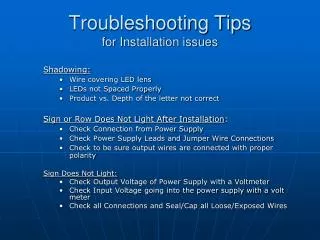
Hardware failures Not very common On MM, look under I/O Module Tasks -> Power/Restart to see diagnostic code after reboot. Also look at fault LED on the Ethernet Switch Module Software Failures Not very common As with all products, software bugs do exist Reference the latest code readme file for a list of resolved bugs with each release of code Misconfiguration of Ethernet Switch Module or other component This is the most common issue encountered Often requires close cooperation between different administrative groups to resolve Problem determination: Ethernet switch I/O modules
Ethernet switch modules: Configuration issues • Most common issue encountered • May be with the Ethernet Switch Module, a device upstream or the server within the BladeCenter • May also be misconfiguration on the Management Module • Same tools used to troubleshoot configuration issues can also be used to help isolate broken hardware and software bugs • Usually requires close cooperation between network administrators and server administrators • Often helps to have special tools (for example, network sniffer) to understand and resolve problem
Do not attach cables to the ESM until both sides of the connection are configured Do not put the blade servers on the VLAN that the ESM uses for its management VLAN interface Make sure the ESM firmware (IOS) code is upgraded Decide the ESM management path (via Management Module or ESM uplinks) and configure for it Ethernet switch modules: Basic rules
BladeCenter management interfaces • Best practices • Troubleshooting and problem determination • BladeCenter management interfaces • Firmware updates and settings • Information gathering • IBM BladeCenter support resources
BladeCenter AMM: System status screen Main information window Navigation menu
System Event Log (SEL) screen • This screen shows event history of the BladeCenter
This screen shows information relating to the hardware in the BladeCenter Hardware Vital Product Data (VPD)
Rules for I/O module management • In-band management • Use the AMM path to an I/O module • Provides centralized management of all I/O modules • All activities and reporting is through a single Ethernet port • Makes LAN configuration easier • Requires MM and all I/O modules to be on the same IP subnet • Out-of-band management • Requires enablement of external management over all ports • May require management VLAN configuration • Access will involve many Ethernet ports • I/O module need not be on the same IP subnet as the MM • If subnets are different, AMM path to I/O module is unavailable
Fibre Channel switch module Web interface • SAN Utility (QLogic) • Full Function GUI • SAN Browser (Qlogic) • Limited functionality • Switch Explorer (Brocade) • Limited functionality
Firmware updates and settings • Best practices • Troubleshooting and problem determination • BladeCenter management interfaces • Firmware updates and settings • Information gathering • IBM BladeCenter support resources
UpdateXpress CD-ROM package • UpdateXpress • Bootable CD-ROM • Supports maintenance of system firmware and Windows device drivers • Automatically detects current device-driver and firmware levels • Gives the option of selecting specific upgrades or allowing UpdateXpress to update all of the system levels it detected as needing upgrades • Can be installed using local DVD or over network using the AMM
UpdateXpress firmware update scripts • UpdateXpress Firmware Update Scripts for BladeCenter (UXBC) • Process that enables firmware updates to be run in a remote, unattended fashion • Requires a management station and supporting software • Windows or Linux OS • FTP and TFTP servers somewhere on the management LAN • UXBC discovery and deployment components • For more information, see • http://www-03.ibm.com/systems/management/uxs.html