Download
1 / 11
700 likes | 1.92k Views
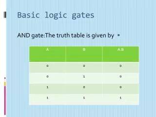
Lecture Notes – Lab 1. Basic logic gates. And Gate. Or Gate. Lecture Notes – Lab 1. Basic logic gates. Inverter. NAND. Elementary Theorem - Identity. X*1 = X; X*0 = 0. X + 1 = 1; X + 0 = X. Other Theorem Commutative: x*y=y*x, x+y=y+x

E N D
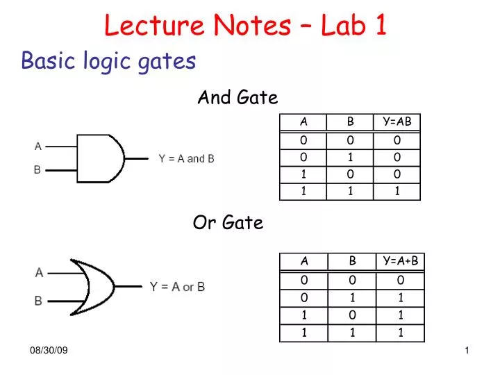
Lecture Notes – Lab 1 Basic logic gates And Gate Or Gate
Lecture Notes – Lab 1 Basic logic gates Inverter NAND Elementary Theorem - Identity X*1 = X; X*0 = 0 X + 1 = 1; X + 0 = X
Other Theorem Commutative: x*y=y*x, x+y=y+x Associative: x*(y*z)=(x*y)*z x+(y+z)=(x+y)+z Distributive: x*(y+z)=x*y+x*z x+y*z=(x+y)*(x+z) Absorption: x+x*y=x x*(x+y)=x Lecture Notes – Lab 1
Other Theorem Combining: x*y+x*y'=x, (x+y)(x+y')=x DeMorgan's theorem:(x*y)'=x'+y' (x+y)'=x'+y' x+x'y=x+y x(x'+y)=xy Consensus: xy+yz+x'z=xy+x'z (x+y)(y+z)(x'+z)=(x+y)(x'+z) Lecture Notes – Lab 1
Lecture Notes – Lab 1 Example 1 Design a circuit for the following function: F3= (Y + Z') X + X'YZ=XY + XZ’ + X’YZ F3=X'YZ+XY'Z'+XYZ'+XYZ=M3+M4+M6+M7 F3 equals 1 when XY or XZ’ or X’YZ equals 1 Is it the simplist? Note: every row of a truth table with a one in the output column is called a minterm
Lecture Notes – Lab 1 K-maps The idea behind a Karnaugh Map (Karnaugh, 1953) is to draw an expression’s truth table as a matrix in such a way that each row and each column of the matrix puts the minterms that differ in the value of a single variable adjacent to each other. • Basic Rules • Every minterm must be inside at least one rectangle, but there must not be any zeros inside any rectangles. • Every rectangle has to be as large as possible. • Rectangles may wrap around to include cells in both the leftmost and rightmost columns. Likewise for the top and bottom rows. • The number of minterms enclosed in a rectangle must be a power of two (1, 2, 4, 8, or 16 minterms for 4-variable maps).
Lecture Notes – Lab 1 Design an AND/OR circuit F3= YZ + XZ' Layout diagram - position on the breadboard Logic diagram
Lecture Notes – Lab 1 Lab 1 task: Simplify the function F = A'B'D + BC'D + A'BC + ACD,and design a circuit for the simplified function using any 7400 logic you wish. Step 1: Draw the Truth Table Step 2: Simplify the Equation Step 3: Draw the logic diagram performing the Equation in Step 2 Step 4: Draw the corresponding layout diagram Step 5: Implement the circuit
Step 1: Truth Table corresponding to F = A'B'D + BC'D + A'BC + ACD
Step 2: Simplify the Equation 1- Maps the TT to K-map CD AB 2- Simplify the boolean function A’D CD AB A’BC BD CD
Step 3: Draw the logic diagram F = A’BC + BD + CD + A’D Step 4: Draw the layout diagram Step 5: Implement the circuit