Download
1 / 18
220 likes | 1.44k Views
Takeoff Performance Jet Aircraft Performance. Lecture 11 Chapter 5. Takeoff. Takeoff Distance is the distanced required to accelerate from zero airspeed up to, or above, stall speed. The four forces are not in balance during takeoff. (fig. 5-21 p. 139)

E N D
Takeoff PerformanceJet Aircraft Performance Lecture 11 Chapter 5
Takeoff • Takeoff Distance is the distanced required to accelerate from zero airspeed up to, or above, stall speed. • The four forces are not in balance during takeoff. (fig. 5-21 p. 139) • Acceleration equals force divided by mass • Net force is in the direction of acceleration • The net force is equal to thrust minus drag & frictional force.
Favorable Aircraft Takeoff Conditions • High thrust • Low drag • Low runway tire friction • Low weight • High wing area • High lift coefficient
Takeoff Thrust • Thrust is greatest when air density is highest • Although higher density increased drag, the increase in thrust is greater; the stall speed decreases • High density, which results from high pressure & low temperature , works favorably for takeoff
Favorable Environmental Takeoff Conditions • Smooth runway surface • Level or downhill slope • High pressure • Low temperature • High headwind
Balance Field Length Critical engine failure speed-V1 definite criterion for decision Slower than V1 the pilot aborts the takeoff to stop in the event of an engine failure If an engine fails faster than V1 the pilot must continue the takeoff on remaining engines
Balanced Field • V2 is the distance required to stop is exactly the same as that required to reach takeoff speed • Balanced field length is the overall runway distance up to the point of stopping • Figure 5-22 p. 143
Landing • Landing in two parts- landing distance & roll distance from touchdown to stop • Touchdown at 15% above stall is appropriate for modern aircraft. • Deceleration is negative acceleration • Most effective braking only reduced roll 10% than with no braking
Landing Conditions • Runway surface • L/D ratio • Wind • Runway slope • Altitude (pressure & temperature) • Weight
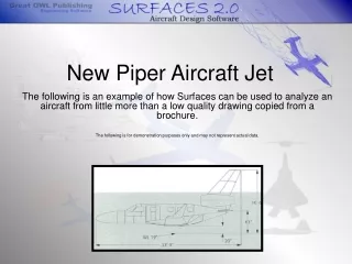
Jet Aircraft Performance • Jet-propelled aircraft produce thrust directly from the engine. • Figure 5-23 p. 146 • Plot of thrust available and thrust required • The maximum velocity occurs at the intersection of these curves (like power curve)
Range & Endurance • Because fuel consumption is proportional is to thrust, the minimum fuel consumption would occur at the minimum thrust required • Best endurance occurs at the minimum point on the thrust required (drag) curve • Figure 5-24 p. 147
L/D Ratio • Maximum L/D ratio gives the maximum performance in the following: • Endurance • Power-off Glide Ratio • Angle of Climb
Takeoff • Vs -stall speed in takeoff configuration • Vmc –minimum control speed for one engine out • V1 –decisionspeed for engine out • Vr – rotation speed • Vmu –min. unstick speed were safe flight possible • Vlof – proper liftoff • V2 – takeoff climb speed to be reached 35ft alt.
Maneuvering Load factors limits established by the FAA A load factor is the maneuver force in a particular direction divided by the weight of the aircraft The load factor is the lift divided by the weight in the vertical direction
V-n Diagram • V-n diagram is the aircraft operational envelope that ensures design loads are not exceeded • The diagram is simply a plot of velocity for various load factors • Figure 5-27 p. 151
Accelerated Climb • Rate of climb-excess power divided by weight (Specific excess power) • “Specific” denotes some quantity per unit • Figure 5-28 p. 153 • Figure 5-29 p. 154 • Figure 5-30 p. 155
Quiz on Chapter 5 Please take out a sheet of paper Include today’s date & your name
Quiz on chapter 5 • Explain balance of field. • What is a load factor? • What is the purpose of the V-n diagram?