Download
1 / 16
160 likes | 177 Views
Tri-roller or roll stake swaging tools have developed as an improvement to the traditional methods of Anvil or 2 wheel swaging. The Tri Roller or Roll Stake swaging tool offers the advantage of allowing the 3 rolling elements in the tool to better contact the V Groove surface of the bearing at the correct angle allowing the V Groove to fold over into the housing. To Know More Visit: http://www.carterbearings.co.uk/aerospace-bearing-tools/

E N D
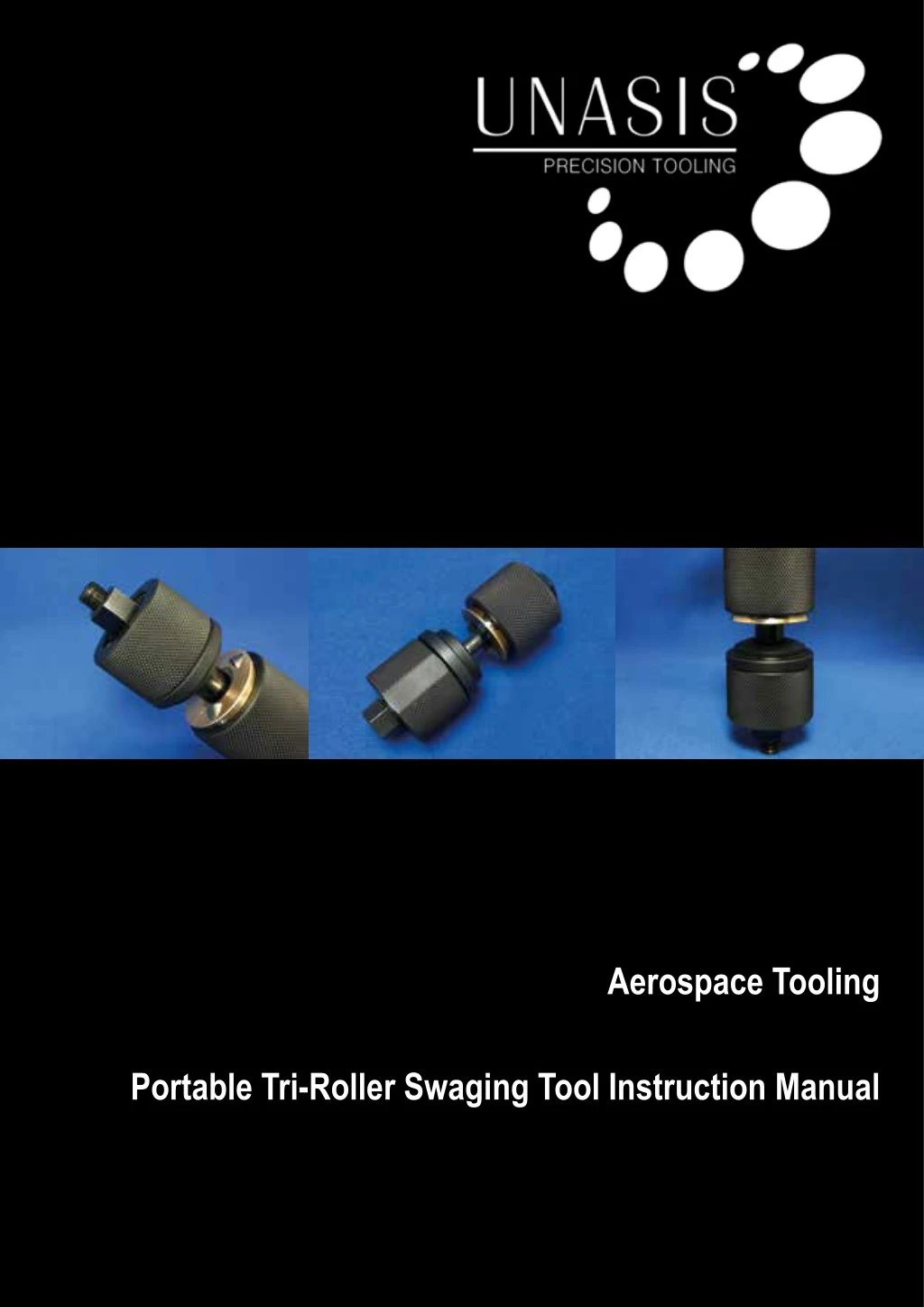
Aerospace Tooling Portable Tri-Roller Swaging Tool Instruction Manual
GLOBAL MASTER DISTRIBUTOR: GLOBAL MASTER DISTRIBUTOR: Carter Manufacturing Limited Carter Manufacturing Limited TEL: +44 (0)1865 821 720 EMAIL: sales@carterbearings.co.uk TEL: +44 (0)1865 821 720 EMAIL: sales@carterbearings.co.uk 1 sales@unasisbearings.com www.unasisbearings.com Tel: +44 (0) 1235 527 770 2 sales@unasisbearings.com www.unasisbearings.com Tel: +44 (0) 1235 527 770
Table of Contents Table of Figures .................................................................... 4 Part List ................................................................................ 5 Tool Component Breakdown ................................................ 6 Bearing Terminology ............................................................ 6 Precautions Prior to Use ................................................... 7 Unasis Portable Tri-Roller Swaging Tool Primary Swage ..................................................................... 8 Set-Up Instructions ......................................................... 8 Operating Instructions .................................................... 10 Step 1 – Tighten Hex Nut .......................................... 10 Step 2 – Rotate Roller Fixture Assembly ................... 10 Step 3 – Repeat Steps 1 and 2 ................................. 10 Step 4 – Inspect Swage ............................................. 10 Secondary Swage ................................................................ 11 Unasis Portable Proof Load Tool Set-Up Instructions ......................................................... 11 Operating Instructions ..................................................... 12 Step 1 – Tighten Hex Nut .......................................... 12 Step 2 – Rotate Roller Fixture Assembly ................... 12 Step 3 – Repeat Steps 1 and 2 ................................. 12 Step 4 – Inspect Swage ............................................. 12 Unasis Breakaway Torque Tool 3 sales@unasisbearings.com www.unasisbearings.com Tel: +44 (0) 1235 527 770
Table of Figures Figure 1 - Portable Tri-Roller Swaging Tool ........................................................................................................................... 5 Figure 2 - Tool component breakdown .................................................................................................................................. 6 Figure 3 - Bearing terminology .............................................................................................................................................. 6 Figure 4 - Disassemble tool using spanner on hex nut ......................................................................................................... 8 Figure 5 - Remove plastic spacer from assembly................................................................................................................... 8 Figure 6 - Flip ring in primary anvil position ........................................................................................................................... 9 Figure 7 - Draw rod inserted through bearing bore ............................................................................................................... 9 Figure 8 - Keyway and flat aligned to assemble tool ............................................................................................................ 9 Figure 9 - Hex nut tightened until tool is finger tight .............................................................................................................. 9 Figure 10 - Tighten hex nut approximately 30 degrees ......................................................................................................... 10 Figure 11 - Rotate roller fixture assembly clockwise ............................................................................................................. 10 Figure 12 - Inspect swage with feeler gauge ......................................................................................................................... 10 Figure 13 - Inspect swage to ensure no smearing or galling is present ................................................................................ 10 Figure 14 - Draw rod inserted through bearing bore ............................................................................................................. 11 Figure 15 - Flip ring in secondary anvil position .................................................................................................................... 11 Figure 16 - Keyway and flat aligned to assemble tool ........................................................................................................... 11 Figure 17 - Hex nut tightened until tool is finger tight ............................................................................................................ 11 Figure 18 - Hex nut tightened approximately 30 degrees ..................................................................................................... 12 Figure 19 - Roller fixture assembly rotated clockwise ........................................................................................................... 12 Figure 20 - Unasis Portable Proof Load Tool and Unasis Breakaway Torque Tool, respectively .......................................... 12 4 sales@unasisbearings.com www.unasisbearings.com Tel: +44 (0) 1235 527 770
Part List Figure 1 - Portable Tri-Roller Swaging Tool 5 sales@unasisbearings.com www.unasisbearings.com Tel: +44 (0) 1235 527 770
Tool Component Breakdown Tool Component Breakdown Tool Component Breakdown Number 1 2 3 4 5 6 7 Tool Component Hex Nut Locating Feature Flip Ring Plastic Spacer Draw Rod Roller Roller Fixture Assembly Figure 2 - Tool component breakdown 1. Hex Nut 2. Locating Feature 3. Flip Ring 4. Plastic Spacer 5. Draw Rod 6. Roller 7. Roller Fixture Assembly 1. Hex Nut 2. Locating Feature 3. Flip Ring 4. Plastic Spacer 5. Draw Rod 6. Roller 7. Roller Fixture Assembly Bearing Terminology Bearing Terminology Bearing Terminology Figure 3 - Bearing terminology 6 sales@unasisbearings.com www.unasisbearings.com Tel: +44 (0) 1235 527 770
Precautions Prior to Use The bearing must be properly installed and centred in the housing using an install/remove tool before swaging. Ensure the housing has suitable clearance for tool operation to be performed. Make sure all contact surfaces are clean and free of debris. Application of a light machine oil is advised. 7 sales@unasisbearings.com www.unasisbearings.com Tel: +44 (0) 1235 527 770
Primary Swage Set-Up Instructions Disassemble tool by unscrewing the hex nut (1) on the locating fixture (2). Remove plastic spacer (4) from between the roller fixture assembly (7) and flip ring (3). Place flip ring (3) into locating fixture (2) with the flat side facing out designated as the primary anvil position. Figure 4 - Disassemble tool using spanner on hex nut Figure 5 - Remove plastic spacer from assembly 8 sales@unasisbearings.com www.unasisbearings.com Tel: +44 (0) 1235 527 770
Insert draw rod (5) into the bore of the bearing until the rollers (6) are seated on the v-groove of the bearing. Align flat on draw rod (5) with matching keyway within locating fixture (2). NOTE: ENSURE THE FLIP RING IS IN PRIMARY ANVIL POSITION. Tighten hex nut (1) until the rollers (6) are seated against the v-groove of the bearing and flip ring (3) is flush against the housing. Figure 6 - Flip ring in primary anvil position CAUTION: OVER-TIGHTENING CAN CAUSE ROLLERS TO DENT OR MAKE AN IMPRESSION ON THE V-GROOVE OF THE BEARING. Rotate roller fixture assembly (7) by hand to ensure there are no restrictions. Figure 7 - Draw rod inserted through bearing bore Figure 8 - Keyway and flat aligned to assemble tool Figure 9 - Hex nut tightened until tool is finger tight 9 sales@unasisbearings.com www.unasisbearings.com Tel: +44 (0) 1235 527 770
Operating Instructions Step 1 – Tighten Hex Nut Tighten hex nut (1) clockwise approximately 30 degrees causing rollers (6) to apply a small amount of pressure on v-groove. Figure 10 - Tighten hex nut approximately 30 degrees NOTE: PRESSURE BETWEEN ROLLERS AND V-GROOVE SHOULD BE LIGHT ENOUGH TO ALLOW HAND ROTATION. Step 2 – Rotate Roller Fixture Assembly Rotate roller fixture assembly (7) three complete revolutions or until it rotates without resistance. NOTE: A SPANNER CAN BE USED ON TOP OF THE ROLLER FIXTURE ASSEMBLY TO ASSIST WITH ROTATING THE ASSEMBLY. ENSURE SPANNER IS ROTATED CLOCKWISE. Figure 11 - Rotate roller fixture assembly clockwise Step 3 – Repeat Steps 1 and 2 Repeat Step 1 and Step 2 until the hex nut (1) is rotated approximately 180° or until the v-groove is completely swaged. NOTE: A COMPLETE SWAGE IS DEFINED BY A 0.002”- 0.005” GAP OR THE GIVEN MANUFACTURER SPECIFICATION. Figure 12 - Inspect swage with feeler gauge Step 4 - Inspect Swage Inspect v-groove to ensure the swage is complete and within specification. Inspect bearing to ensure no smearing or galling is present on the v-groove surface. Figure 13 - Inspect swage to ensure no smearing or galling is present 10 sales@unasisbearings.com www.unasisbearings.com Tel: +44 (0) 1235 527 770
Secondary Swage Set-Up Instructions Insert draw rod (5) into the bore of the bearing, on the opposite side as previously swaged, until the rollers (6) come into contact with the v-groove of the bearing. Rotate flip ring (3) to secondary anvil position. Align keyway on draw rod (5) with matching keyway within locating fixture (2). Figure 14 - Draw rod inserted through bearing bore NOTE: ENSURE THE FLIP RING IS IN SECONDARY ANVIL POSITION Tighten hex nut (1) until the rollers (6) are seated against the v-groove of the bearing and flip ring (3) is flush against the v-groove. CAUTION: OVER-TIGHTENING CAN CAUSE ROLLERS TO DENT OR MAKE AN IMPRESSION ON THE V-GROOVE OF THE BEARING. Rotate roller fixture assembly (7) by hand to ensure there are no restrictions. Figure 15 - Flip ring in secondary anvil position Figure 16 - Keyway and flat aligned to assemble tool Figure 17 - Hex nut tightened until tool is finger tight 11 sales@unasisbearings.com www.unasisbearings.com Tel: +44 (0) 1235 527 770
Operating Instructions Step 1 – Tighten Hex Nut Tighten hex nut (1) clockwise approximately 30 degrees causing rollers (6) to apply a small amount of pressure on v-groove. NOTE: PRESSURE BETWEEN ROLLERS AND V-GROOVE SHOULD BE LIGHT ENOUGH TO ALLOW HAND ROTATION. Figure 18 - Hex nut tightened approximately 30 degrees Step 2 – Rotate Roller Fixture Assembly Rotate roller fixture assembly (7) three complete revolutions or until it rotates without resistance. NOTE: A SPANNER CAN BE USED ON TOP OF THE ROLLER FIXTURE ASSEMBLY TO ASSIST WITH ROTATING THE ASSEMBLY. ENSURE SPANNER IS ROTATED CLOCKWISE. Step 3 – Repeat Steps 1 and 2 Repeat Step 1 and Step 2 until the hex nut (1) is rotated approximately 180° or until the v-groove is completely swaged. Figure 19 - Roller fixture assembly rotated clockwise NOTE: A COMPLETE SWAGE IS DEFINED BY A 0.002”- 0.005” GAP OR THE GIVEN MANUFACTURER SPECIFICATION. Step 4 - Inspect Swage Inspect v-groove swage as previously explained to ensure swage is within manufacture’s specification. NOTE: REASSEMBLE TOOL IMMEDIATELY AFTER COMPLETION TO ENSURE NO COMPONENTS ARE MISPLACED. NOTE: YOUR BEARING IS NOW FULLY INSTALLED AND READY FOR INSPECTION TESTS WITH THE USE OF UNASIS PORTABLE PROOF LOAD TOOL AND UNASIS BREAKAWAY TORQUE TOOL. Figure 20 - Unasis Portable Proof Load Tool and Unasis Breakaway Torque Tool, respectively. 12 sales@unasisbearings.com www.unasisbearings.com Tel: +44 (0) 1235 527 770
Notes 13 sales@unasisbearings.com www.unasisbearings.com Tel: +44 (0) 1235 527 770
Notes 14 sales@unasisbearings.com www.unasisbearings.com Tel: +44 (0) 1235 527 770
This catalogue has been produced with a great amount of care and attention; all data has been checked for its accuracy. However, no liability can be assumed for any incorrect or incomplete data. Due to the constant development and expansion of the product range, we reserve the right to make modifications without prior notice. All rights reserved. Reproduction in whole or in part without authorisation is prohibited. 15 sales@unasisbearings.com www.unasisbearings.com Tel: +44 (0) 1235 527 770
UNASIS INTERNATIONAL LIMITED UNIT 7, ISIS COURT, WYNDYKE FURLONG ABINGDON BUSINESS PARK ABINGDON OXFORDSHIRE OX14 1DZ UNITED KINGDOM TEL: +44 (0)1235 527 770 EMAIL: sales@unasisbearings.com WEBSITE: www.unasisbearings.com