Download
1 / 28
280 likes | 454 Views
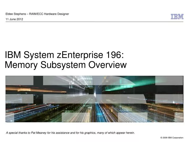
Eldee Stephens – RAIM/ECC Hardware Designer 11 June 2012. IBM System zEnterprise 196: Memory Subsystem Overview. A special thanks to Pat Meaney for his assistance and for his graphics, many of which appear herein. Why System z Today?. IBM System zEnterprise 196 Memory Subsystem Overview.

E N D
Eldee Stephens – RAIM/ECC Hardware Designer 11 June 2012 IBM System zEnterprise 196:Memory Subsystem Overview A special thanks to Pat Meaney for his assistance and for his graphics, many of which appear herein.
Why System z Today? IBM System zEnterprise 196 Memory Subsystem Overview The most secure, the most reliable commercial machine on Earth! • System z is the most available platform you can buy (99.999%) • The security on System z is unsurpassed by any other platform • Stringent Service Level Agreements The backbone of data processing in large enterprise environments A large portion of today’s operational data resides on the mainframe – and it's growing.... Workload management for mixed workloads Manage multiple workload types with priority and work types scheduling Lower costs through reduced complexity Simplified management Reduced environmental costs Greater flexibility to meet changing needs
But what if something goes wrong? IBM System zEnterprise 196 Memory Subsystem Overview • IBM System z environments host mission-critical applications: going down is not an option! • A typical big-box retailer can lose $100,000s of business for every minute of downtime • A typical credit card transaction processor can lose $1,000,000s of business for every minute of downtime • Typical distributed systems measure intervals between service interruptions in days • Typical mainframe environments measure intervals between service interruptions in years – and that's still not good enough • On the mainframe, reliability isn't just a feature: it's a design philosophy
… the answer is RAS: reliability, availability, and serviceability IBM System zEnterprise 196 Memory Subsystem Overview • Every conceivable error scenario and fault must be considered: how to detect, how to heal, how to recover? • Massive design work is undertaken to handle every niggling little potential fault; downtime is not an option! Impact of Outage Increased Focus over time Temperature = Silicon Reliability Worst EnemyWearout = Mechanical Components Reliability Worst Enemy.
z196 System Topology IBM System zEnterprise 196 Memory Subsystem Overview Tremendous capacity possible with tightly-coupled design: • Six CP chips per node; six cores per CP chip • Three memory controllers per node • Memory controller in z196 an all-new design • Five memory channels per MCU • Two cascades of memory cards supported • Differential I/O between memory cards and MCU allows for tremendous bandwidth Mem2 Mem1 Mem0 CP2 CP1 CP0 CP2 CP1 CP0 • 96 total cores • Total system cache • 768 MB shared L4 (eDRAM) • 576 MB L3 (eDRAM) • 144 MB L2 private (SRAM) • 19.5 MB L1 private (SRAM) FBCs FBCs SC1 SC0 CP3 CP4 CP5 CP3 CP4 CP5
z196 Memory Controller – Logical View IBM System zEnterprise 196 Memory Subsystem Overview • Memory controller processes data fetch/store requests and key ops from local L3 controllers • To maximize bandwidth, two independent L3 ports are used, sliced on address • Each memory controller communicates with five memory 'channels,' each of which contains the DRAMs and SuperNova AMB controller; two cascades of memory cards can exist in each channel • Key cache capacity and performance improvements have been made from previous IBM System z mainframes • Vast improvements in recovery from errors over previous systems thanks to our new RAIM system • And we're running pretty brisk, too! Speeds and Feeds: 1.4GHz in MCS, 1.6GHz in MCA 42GB/sec between MCU and L3 24GB/sec store throughput to memory 38GB/sec fetch throughput from memory
z196 Memory Cards – Detailed View IBM System zEnterprise 196 Memory Subsystem Overview
z196 Memory Controller – Physical View IBM System zEnterprise 196 Memory Subsystem Overview • 1 Independent MC per CP • Unused MCs gated to save power • 5 Channels per MC • 5 Lock Step Channels (RAIM) • First four channels consist of data + ECC; fifth channel ECC only • Up to 2 cascades • Channels – 4.8Gb/s • Differential Clock and Data • Packet based CRC • Down Stream • 1 Clock • 13 Data / Command • 2 Spares (1 Spare for Clk) • 6:1 = 12 beats, CRC18 • Up Stream • 1 Clock • 20 Data / Command • 2 Spares (1 Spare for Clk) • 6:1 = 8 beats, CRC16 MCU0 RAIM Ch4 Ch3 ECC Ch2 DRAM DIMM Ch1 Ch0 X CRC X X X CLK Diff X X ASIC ASIC CRC X CLK Diff
z196 Memory Controller – RAS Overview IBM System zEnterprise 196 Memory Subsystem Overview MCU0 RAIM Layers of Memory Recovery ECC • Powerful 90B/64B Reed Solomon code DRAM Failure • Marking technology; no half sparing needed • 2 DRAM can be marked • Call for replacement on third DRAM Lane Failure • CRC with Retry • Data – lane sparing • CLK – RAIM with lane sparing DIMM Failure (discrete components, VTT Reg.) • CRC with Retry • Data – lane sparing • CLK – RAIM with lane sparing DIMM Controller ASIC Failure • RAIM Recovery Channel Failure • RAIM Recovery Ch4 Ch3 ECC Ch2 DRAM DIMM Ch1 Ch0 X CRC X X X CLK Diff X X ASIC ASIC CRC X CLK Diff
z196 Memory Controller – RAS Overview (cont.) IBM System zEnterprise 196 Memory Subsystem Overview Preventing Unscheduled Outages • Advanced Memory RAIM (Redundant Array of Independent Memory) design • Enhanced Reed-Solomon code (ECC) – 90B/64B • Protection against Channel/DIMM failures • Chip marking for fast DRAM replacements • Mirrored Key cache • Improved chip packaging • Continued focus on Firmware Handling Preventable Outages • Double memory data bus lane sparing (reducing repair actions) • Single memory clock bus sparing • Power distribution using N+2 Voltage Transformation Modules (VTM) • Redundant (N+2) Humidity Sensors • Redundant (N+2) Altitude Sensors
z196 MCU Recovery: ECC/RAIM Protection IBM System zEnterprise 196 Memory Subsystem Overview • No need for spare chips! If we 'know' in advance of a location where errors are extant, we 'mark' it. This can be applied on a DRAM or a channel basis. Marking ahead of time allows us to find new errors on top of the known ones. • Marks are much more flexible than spare DRAMs, and can keep the card cost down as well, to say nothing of the reduced design cycle given simpler verification • If we ever reach a threshold where the system can no longer correct dynamically, we 'call home' to let IBM know to replace the defective part; the system continues to operate without performance penalty in the interim • Firmware is always looking at the health of DRAMs in the background
z196 MCU Recovery: ECC/RAIM Protection (cont.) 16B 16B 16B 16B 16B 16B Key Cache Key Cache Key Cache MCU 0 MCU 1 MCU 2 2B 2B 2B DATA CHECK ECC RAIM Parity IBM System zEnterprise 196 Memory Subsystem Overview Level 3 Cache DATA CHECK Extra column provides RAIM function
z196 MCU Recovery: ECC/RAIM Protection (cont.) IBM System zEnterprise 196 Memory Subsystem Overview • Store pipe in MCU calculates ECC across entirety of 64B ECC group • Data is then packaged up on a per-channel basis • RAIM is generated by using a simple set of XOR4s • Any pre-existing error on the data is stamped with an SPUE (special UE) • SPUEs allow us, on subsequent fetches, to know that the error did not originate in memory and/or that the error is not new • They also enable us to avoid going into recovery in the core, and demanding a refetch of the data • The SPUE codepoint is such that, if new errors occur on top, we can detect that properly Store Data Store Data Store Data Store Data ECC Gen ECC Gen ECC Gen ECC Gen Chan0 Data Chan1 Data Chan2 Data Chan3 Data RAIM PTY Chan4 Data CRC Gen
z196 MCU Recovery: ECC/RAIM Protection (cont.) IBM System zEnterprise 196 Memory Subsystem Overview CRC Check Chan0 Data Chan1 Data Chan2 Data Chan3 Data Chan4 Data Marks: • up to 2 Chip • up to 1 DIMM(orig or CRC) RAIM ECC Decoder Logic • Chip marks in are applied according to variable criteria set by designers and/or field feedback as a system ages • Channels with CRC errors are also 'marked' internally, using the RAIM mechanism to apply full channel correction • Marking literally recreates the data ex nihilo within the decoder; it doesn't use the bad data during this process Corrected Data 64 Bytes ECC Status Status: • CE? UE? SPUE? • Full isolation down to the DRAM of where the errors occurred • New errors can kick off firmware-initiated chip marking
z196 MCU Recovery: Bus CRC Errors IBM System zEnterprise 196 Memory Subsystem Overview Downstream Data/Commands: • CRC18 is generated on 12-beat packets • 156/138 packet size • CRC generated across all three blocks and sent in last portion of frame • Errors detected by memory card, forwards poison CRC code back to MCU to initiate CRC recovery Upstream Data: • CRC16 is generated on 8-beat packets • 160/144 packet size • 18 bytes x 5 channels = 90 Bytes • Must wait for all data before seeing CRC error • If error seen, if only in one channel, RAIM can be used for full channel correct • Otherwise CRC recovery initiated Chan0 Data CRC 18 Chan0 Data
z196 MCU Recovery: Bus Error Recovery (Tier 1) IBM System zEnterprise 196 Memory Subsystem Overview MCU Error Detection Normal (powedown) Error Detection New Stores New Fetches Poison CRC up to MC Poison CRC up to MC MC Retry Resend Stores MC Retry Resend Stores MC Halts new ops MC Halts new ops Stores Pending Fetches Pending STR-> Powerdown STR-> Powerdown Tier 1 Retry MC Waits for prev ops to complete MC Waits for prev ops to complete IFC MC Sends DS Poison CRC MC Sends DS Poison CRC SN0 SN0 SN0 SN0 SN0 SN0 SN1 SN1 SN1 SN1 SN1 MC Sends Error Ack MC Sends Error Ack 5 Wait 550 cycles (Establish STR) Wait 550 cycles (Establish STR)
z196 MCU Recovery: Bus Error Recovery (Tier 2) IBM System zEnterprise 196 Memory Subsystem Overview • Escalation to higher tiers of recovery depends on rate of errors seen • The MCU watches and counts the number of errors in a given time window and also if previous attempts eliminated the errors or not • If still firing, we escalate to tier 2, where we effectively re-init the channel taking the error • Typically this will also involve a clock failover Normal Operation Error Detection Poison CRC up to MC MC Retry Resend Stores MC Halts new ops STR-> Powerdown Tier 1 Retry MC Waits for prev ops to complete MC Sends DS Poison CRC MC Sends Error Ack 4 5 5 N Y Chan Trouble? Wait 550 cycles (Establish STR) 1 Degrade bad channel 5 5 TS2-TS7 Tier 2 Fast Init
z196 MCU Recovery: Bus Error Recovery (Tier 3) IBM System zEnterprise 196 Memory Subsystem Overview RAIM Degraded Normal Operation Error Detection Call Home Channel Degrade Poison CRC up to MC MC Retry Resend Stores MCU Scrub pass complete MC Halts new ops STR-> Powerdown Subsequent Channel error Tier 1 Retry Start MCU Scrub Pass MC Waits for prev ops to complete Successful 5 5 Fail 4 MC Sends DS Poison CRC TS2-TS7 5 channels N Y Chan Trouble? Quiesce channels Force FastInit 1 MC Sends Error Ack 1 Wait (hang check) 4 TS2-TS7 Tier 3 RAIM-Degraded SlowInit Tier 2 Link FastInit 5 Wait 550 cycles (Establish STR) 1 TS0 bad channel Recently in Tier 2 Tier 3 GOAL: Use TS0 to clean up clocks and reset SN hardware
z196 MCU Recovery: Bus Error Recovery Summary IBM System zEnterprise 196 Memory Subsystem Overview Store Errors: • Before retiring the queue, wait a fixed number of cycles for receipt of poison CRC code; if none received, operation successful • If poison CRC received in given window, begin CRC recovery • Retry the store that received the error and any fetches that would have been in flight during CRC recovery Fetch Errors: • If bad CRC calculated on fetch data frame, and error is limited to one and only one channel, and no other channel mark extant, we can internally act as though that channel is 'marked,' using RAIM to reconstruct the data for the channel with bad CRC • For retry mechanism we rely on the core: if it receives bad data (UE), it will refetch the line itself; this saves hardware in the MCU, but adds latency for retrying fetches that return with uncorrectable errors • Keys are 'mirrored' across a 64B basis. For every 128B key fetch, you get two copies of the same 64B set of keys; if a key fetch has a UE, we look at the 'mirrored' copy; otherwise it's treated like a normal demand fetch from the recovery standpoint
z196 MCU RAS Summary IBM System zEnterprise 196 Memory Subsystem Overview
How Does Something Like This Get Designed? IBM System zEnterprise 196 Memory Subsystem Overview Product Engineering Research Group Logic Design and uArch RAS Council Firmware Verification HW Bringup and Test
Backup Pictures IBM System zEnterprise 196 Memory Subsystem Overview
IBM System zEnterprise 196 Memory Subsystem Overview z196 Air cooled – Under the covers (Model M66 or M80) Front view Processor Books, Memory, MBA and HCA cards Internal Batteries (optional) Ethernet cables for internal System LAN connecting Flexible Service Processor(FSP) cage controller cards Power Supplies 2 x Support Elements InfiniBand I/O Interconnects I/O cage 2 x Cooling Units (MRUs) PCIe I/O drawers Optional FICON & ESCON FQC – not shown
IBM System zEnterprise 196 Memory Subsystem Overview z196 Water cooled – Under the covers (M66 or M80) front view Ethernet cables for internal System LAN connecting Flexible Service Processor(FSP) cage controller cards Internal Batteries (optional) Power Supplies Processor Books, Memory, MBA and HCA cards Support Elements InfiniBand I/O Interconnects I/O cage 2 x Water Cooling Units I/O drawers
z196 Multi-Chip Module (MCM) Packaging • CMOS 12s chip Technology • PU, SC, S chips, 45 nm • 6 PU chips/MCM – Each up to 4 cores • One memory control (MC) per PU chip • 23.498 mm x 21.797 mm • 1.4 billion transistors/PU chip • L1 cache/PU core • 64 KB I-cache • 128 KB D-cache • L2 cache/PU core • 1.5 MB • L3 cache shared by 4 PUs per chip • 24 MB • 5.2 GHz • 2 Storage Control (SC) chip • 24.427 mm x 19.604 mm • 1.5 billion transistors/SC chip • L4 Cache 96 MB per SC chip (192 MB/Book) • L4 access to/from other MCMs • 4 SEEPROM (S) chips • 2 x active and 2 x redundant • Product data for MCM, chips and other engineering information • Clock Functions – distributed across PU and SC chips • Master Time-of-Day (TOD) function is on the SC • 96mm x 96mm MCM • 103 Glass Ceramic layers • 8 chip sites • 7356 LGA connections • 20 and 24 way MCMs • Maximum power used by MCM is 1800W PU 2 PU 1 PU 0 S10 S00 SC 1 SC 0 S11 S01 PU 3 PU 4 PU 5
z196 Quad Core PU Chip Detail • Up to Four active cores per chip • 5.2 GHz • L1 cache/ core • 64 KB I-cache • 128 KB D-cache • 1.5 MB private L2 cache/ core • Two Co-processors (COP) • Crypto & compression accelerators • Includes 16KB cache • Shared by two cores • 24MB eDRAM L3 Cache • Shared by all four cores • Interface to SC chip / L4 cache • 41.6 GB/sec to each of 2 SCs • I/O Bus Controller (GX) • Interface to Host Channel Adapter (HCA) • Memory Controller (MC) • Interface to controller on memory DIMMs • Supports RAIM design • 12S0 45nm SOI Technology • 13 layers of metal • 3.5 km wire • 1.4 Billion Transistors • Chip Area – 512.3mm2 • 23.5mm x 21.8mm • 8093 Power C4’s • 1134 signal C4’s
L4 Cache (24MB) L4 Cache (24MB) Fabric IOs L4 Controller Fabric IOs Perv Data Bit- Stack Data Bit- Stack PLL ETR/ TOD Clk Repower Perv Perv L4 Cache (24MB) L4 Cache (24MB) z196 SC Chip Detail 12S0 45nm SOI Technology 13 layers of metal Chip Area – 478.8mm^2 24.4mm x 19.6mm 7100 Power C4’s 1819 signal C4’s 1.5 Billion Transistors 1 Billion cells for eDRAM eDRAM Shared L4 Cache 96 MB per SC chip 192 MB per Book 6 CP chip interfaces 3 Fabric interfaces 2 clock domains 5 unique chip voltage supplies
z196 Book Layout 8 I/O FAN OUT 2 FSP MCM @ 1800W Refrigeration Cooled or Water Cooled 16X DIMMs 100mm High Backup Air Plenum MCM Fanout Cards Front Memory Rear Memory DCA Power Supplies 3xDCA 11 VTM Card Assemblies 8 Vertical 3 Horizontal 14X DIMMs 100mm High Cooling from/to MRU z196TLLB28