Download
1 / 24
240 likes | 483 Views
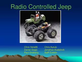
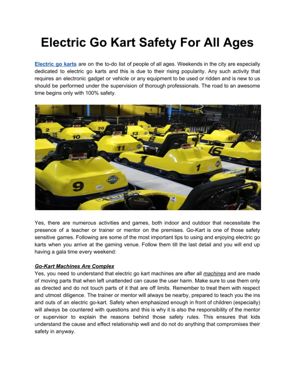
Radio Controlled Go-Kart. Paul Kramer David Shan ECE 345 Spring 2001 Professor: Gary Swenson TA: Wojciech Magda. Meet Gumby II. 7 foot by 3.5 foot frame 16 inch tires, rear wheel drive, locked axle Independent front spring suspension 10 HP Tecumseh Engine with 12 volt, 7 amp alternator

E N D
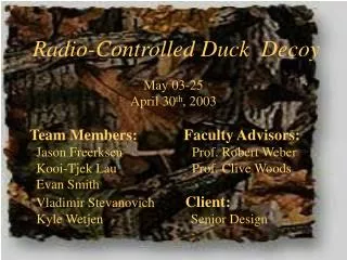
Radio Controlled Go-Kart Paul Kramer David Shan ECE 345 Spring 2001 Professor: Gary Swenson TA: Wojciech Magda
Meet Gumby II • 7 foot by 3.5 foot frame • 16 inch tires, rear wheel drive, locked axle • Independent front spring suspension • 10 HP Tecumseh Engine with 12 volt, 7 amp alternator • 40 MPH top speed • 200 lb curb weight
Objective • Goal: Transform Gumby II into a radio controlled go-kart. • Design and implement all necessary electronic and mechanical sub-systems for each primary function: • Throttle • Steering • Braking • Systems must be reliable and durable to withstand real world use, including abuse and violent vibration.
Presentation Outline • Discuss Design Basics • Design Details • RC Radio • HC12 • Power Amp • Motors/Mechanics • HC12 Software • Problems and Solutions • Questions and Comments
Design Basics • A standard RC model radio receives an FM radio signal from its matching transmitter. • Signals are passed to an HC12 micro-controller, which serves as the “brain” of the go-kart. • Using feedback, the HC12 produces control signals which are sent to a large power amp. • The power amp drives electric motors which service the physical functions (steering, brake). • Throttle control is handled with a small scale, standard RC model servo directly connected to the radio receiver. • All blocks are implemented as modular components to partition the overall design, ease integration, and provide a durable package.
Top Level Schematic Rear End of Vehicle Front End of Vehicle 10K potentiometer Steering motor Throttle Servo SIG (20) 5VDC (18) SIG (20) 5VDC (20) LGND (20) + (18) - (18) LGND (18) start (12) 12VDC (18) stPWM (20) Gasoline Engine & Alternator Engine/Power Control HC12Radio5VDC Reg. Dual Amp stDIR (20) LGND (18) stop (18) BKPWM (20) bkDIR (20) alternator (18) 5VDC (18) LGND (18) GND (16) GND (12) 12VDC (18) PGND (18) 12V Battery / 40A breaker bkSW (20) + (18) - (18) 12VDC (12) Brake Switch Brake Motor LGND (20)
Block Diagram of Control System Transmitter Brake Motor Receiver HC12 Power Amp Throttle Servo Steering Motor
Block Diagram of Power System Engine Control System Power Control 12V Battery
Radio/HC12 Interface Receiver • RC radio is a stand-alone unit and requires no special design other than interfacing with its output. • HC12 must be able to interprete the output of the radio receiver, which is a 56 Hz, 5V logic pulse train with variable pulse width. • Input Capture function of the HC12 is designed for exactly this purpose. HC12
HC12/Power AmpInterface HC12 Power Amp • HC12 must be able to simultaneously signal the power amp to control either of the two motors. • Control of motor speed and direction is necessary. • This is accomplished with two channels of pulse width modulation, supplemented with a direction signal: • Channel 1: DIR, PWM • Channel 2: DIR, PWM • Negative logic is used for PWM signal.
Power Amp Design • Consists of two mirror image circuits, one for each channel (steering and brake) • Control of motor direction is made possible using low resistance MOSFET transistors in an H-bridge configuration. • 5V TTL logic translates the PWM/DIR signals and provides a safe delay to ensure that there is never a direct path from Vdd to Gnd during transistions in the H-bridge. • Alumminum heat sinks dissipate heat into the frame of the go-kart. • Module is fully integrated on a PCB for reliable operation.
Dual Amp: Top Level Schematic Circuit Board 12VDC Power GND(from Engine / Power control 14awg) Input Logic 1 H-Bridge 1 A (+) (–)(to steering motor 14awg) notA stDIRstPWMbkDIRbkPWM(from HC12 20awg) B notB Input Logic 2 H-Bridge 2 A (+)(–)(to brake motor 14awg) notA B notB 5VDCLGND(from HC12 / Radio / Regulator 18awg) CLK Clock Generator
Dual Amp: Input Logic (one per channel) B PWM notB DIR D Q D Q A CLK Qbar CLK Qbar CLK notA D flipflops: 7474AND gates: 7411Inverters: 7404 Dual Amp: Clock Generator 5VDC CLK(1kHz) 8 3 LM555Timer 3.9K 4 7 10uF 0.1uF 2 6 1 5 68K 0.01uF 0.01uF LGND
Dual Amp: H-Bridge (one per channel) 12VDC 470uF 15V 1W 1K 1K 1K 1K 6 7 A 10K 5 8 B 10K 2N2222 MPM3004 2N2222 C 3 9 notB notA 10K 10K B 2 10 4 12 E 2N2222 2N2222 PGND (+) (–)to motor
Steering Mechanics • A 12 volt cordless drill was chosen due to its low cost, built in gearing, and ease of interface. • Metal mounting hardware was designed and fabricated to support the drill. • A small 5k potentiometer is mounted on the steering axis to relay position information back to the HC12. • An alumminum steering arm is attached to the drill, turning two push-rods connected to the front wheel mounts.
Brake Mechanics • A 12 volt cordless drill was used for the brake as well. • Metal mounting hardware was designed and fabricated to support the drill. • An alumminum arm is attached to the drill which pulls the brake cable for the band-drum brake. • The motion of the brake arm is limited by a metal stop plate during the disengagement phase (simplifies HC12 programming)
Power Control Design • Power control module performs several functions: • Master On/Off switch • Routes 12 volt power to Power Amp and HC12/Radio modules • Electric start/stop of Tecumseh engine • Routes alternator current to 12 volt battery • Design is simply a set of switches and a high current relay in a special configuration.
Engine / Power Control SPDT 12V 40A relay 12 awg 12VDC(from battery) 12 awg STARTto gas engine 18 awg STOP 14 awg 18 awg ALT(to gas engine) SPST engine start switch 14awg 12VDC 14 awg PGND(to DUAL AMP) 14 awg GND(from battery) 18 awg 12VDC DPDT system ON/OFF switch 18 awg LGND(to HC12/RADIO) 18 awg LGND(to brake switch)
HC12 Programmingfor Steering • HC12 receives signals from the radio receiver using the Input Capture feature, and it receives signal from the steering potentiometer using the A/D converter. • PWM and DIR outputs use the “P” port of the HC12, which contains special PWM output hardware. • The goal of the HC12 program is to measure the error between the desired steering position and the actual steering position then update the PWM output to the power amp to correct the error.
HC12 programming flow chart Main: Input capture interrupt service routine: Start Start Initialize PWM outputsInitialize A/D Initialize input capture interrupts Rising or falling edge? Rising Store current timervalue into LASTRISE variable Falling Subtract LASTRISEfrom current timervalue; scale and store result; Adjust offset and scalecurrent A/D register value Subtract scaled valuesto create error signal.Determine derivativeof error signal. Return Generate corrective signal by processing error and derivative, update PWMoutputs
HC12 Programmingfor Brake • HC12 receives signals from the radio receiver using the Input Capture feature in the same manner as the steering programming. • When the brake/throttle channel is below a defined theshold, the PWM signal is activated to apply the brake. • When the channel rises above that threshold, a short burst signal is output to reset the brake to its disengaged position. • PWM and DIR outputs use the “P” port of the HC12 (same as steering).
Problems and Solutions • RC Radio interference • FM radio is moderately suceptible to EM interference produced by motor’s ignition system • Solution: Shielding on motor, PCM radio • Power Amp overheating • Original design of the power amp absorbed engine inertia during the off stages of the PWM signal. • Solution: Added logic to implement “neutral” mode during off stages of the PWM signal • Steering system too weak • Steering works fine without a load, but with the load, performance is inadequate. • Solution: Better gearing for motor. Implement integral control within HC12 programming and optimize system parameters for a load.
Questions and Comments Paul Kramer David Shan