Download
1 / 33
360 likes | 534 Views
Introduction to Network Layer. Lesson 09 NETS2150/2850 http://www.ug.cs.usyd.edu.au/~nets2150/. School of Information Technologies. Lesson Outline. Switching is an effective way of sharing network resources Circuit switching Packet Switching. Position of network layer. McGraw-Hill.

E N D
Introduction to Network Layer Lesson 09 NETS2150/2850 http://www.ug.cs.usyd.edu.au/~nets2150/ School of Information Technologies
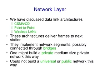
Lesson Outline • Switching is an effective way of sharing network resources • Circuit switching • Packet Switching
Position of network layer McGraw-Hill • The McGraw-Hill Companies, Inc., 2004
Network Layer in an Internetwork Link 1 Link 2 Link 3 McGraw-Hill • The McGraw-Hill Companies, Inc., 2004
transport packet from sending to receiving hosts network layer protocols in every host, router three important functions: path determination: route taken by packets from source to dest. Routing algorithms forwarding: move packets from router’s input to appropriate router output call setup: some network architectures require router call setup along path before data flows network data link physical network data link physical network data link physical network data link physical network data link physical network data link physical network data link physical network data link physical application transport network data link physical application transport network data link physical Network layer functions
Switching in Wide Area Switched Networks McGraw-Hill • The McGraw-Hill Companies, Inc., 2004
Switching Networks • Long distance transmission is typically done over a network of switched nodes • not through dedicated mesh lines • Nodes not concerned with content of data • Data routed by being switched from node to node
Switching Nodes • Switching nodes may connect to other nodes only, or to end systems and other nodes • Some redundant connections are desirable for reliability • Two different switching technologies: • Circuit switching • Packet switching
Circuit Switching • Developed for voice traffic • Provides dedicated communication path between two stations • Connected sequence of links • Resources reserved for exclusive use • Done at the physical layer • Transparent connection • Three phases in communication • Establish • Transfer • Disconnect
Circuit Switching (2) • Connection setup takes time • Once connected, transfer is transparent • Developed for voice traffic (phone)
Public Circuit Switched Network (subscriber line) Twisted-pair Multiple voice frequency circuits Subscribers, subs. Line, exchanges, and trunks
Local call Long-distance call Circuit Establishment Line c + one channel on the trunk to the ex
Circuit switching Disadvantages • Circuit switching designed for voice • Resources dedicated to a particular call • Much of the time a data connection is idle, unused capacity is wasted • Data rate is fixed • Both ends must operate at the same rate Solution: Packet Switching
Packet Switching Principles • Developed for bursty data traffic • Data transmitted in small packets • Typically 1000 octets • Longer messages split into series of packets • Each packet contains a portion of user data plus some control info (header) • Control info • Routing (addressing) info • Packets are received, stored briefly (buffered) and passed on to the next node • Store and forward • Not concerned with the content of the data
A packet’s trip from Src to Dest Destination Source
Packet Switching… Routing table Source and Dest. IP addresses Source and Dest. layer 2 addresses
Advantages • Line efficiency • Single node to node link can be shared by many packets over time • Packets queued and transmitted • Data rate conversion • Each end system connects to the local node at its own speed • Nodes buffer data if required to equalize rates • Packets are accepted even when network is busy (as opposed to call dropping) • Delivery may slow down • Priorities can be used • Based on the priority, some packets can experience less delay
Packet Switching Technique • End system breaks a long message into packets • Packets sent one at a time to the network • Packets handled in two modes: • Datagram used in today’s Internet • Virtual circuit used in ATM, frame-relay, X.25
Datagram Mode: the Internet model • No call setup at network layer • Each packet treated independently • No reference to packets handled before from the same message • no network-level concept of “connection” • Packets can take any practical route • Packets may arrive out of order • Packets may go missing: Best-effort service! • Up to receiver to re-order packets and recover from missing packets
Datagram Mode Illustration Pkt re-ordered Exit node • Packets for same destination may not follow the same • route • May arrive out of sequence • Exit node or the destination does the re-ordering
Virtual Circuit Mode • Preplanned route established before any packets sent • Call request and clear packets to establish and drop circuit (handshake) • Each packet contains a virtual circuit identifier instead of destination address • Every router on source-dest path maintains “state” for each passing virtual circuit (VC) • No routing decisions required for each packet • transport-layer connection only involved two end systems • link, router resources (bandwidth, buffers) may be allocated to VC • to get circuit-like performance. • Non-dedicated path
used to setup, maintain teardown VC used in ATM, frame-relay, X.25 not used in today’s Internet application transport network data link physical application transport network data link physical Virtual circuits: signaling protocols 6. Receive data 5. Data flow begins 4. Call connected 3. Accept call 1. Initiate call 2. incoming call
Packet Size • Packet size and transmission time • Breaking a message into smaller packets • Transmission time drops • Too many smaller packets is not good either! • Processing and queuing delays increase when there are more packets to handle, for a single message
Packet Size & Transmission time… More and smaller packets mean more of the headers, increasing the octet-time 77 octet-times 84 octet-times! 92 octet-times Total tx time: 43*3=129 octet-times
Virtual Circuits vs Datagram • Virtual circuits • Network can provide sequencing and error control • Packets are forwarded more quickly • No routing decisions to make • Less reliable • Loss of a node looses all circuits through that node • Datagram • No call setup phase • Better if few packets • More flexible • Routing can be used to avoid congested parts of the network
Internet data exchange among computers “elastic” service, no strict timing req. “smart” end systems (computers) can adapt, perform control, error recovery simple inside network, complexity at “edge” many link types different characteristics uniform service difficult ATM evolved from telephony human conversation: strict timing, reliability requirements need for guaranteed service “dumb” end systems telephones complexity inside network Datagram or VC network: why?
Circuit v Packet Switching • Performance comparison involves: • Propagation delay • Transmission time • Node processing delay Constant factors Variable factor
Event Timing Sequence Node delay Single block Packetised data
transport packet from sending to receiving hosts network layer protocols in every host, router three important functions: path determination: route taken by packets from source to dest. Routing algorithms forwarding: move packets from router’s input to appropriate router output call setup: some network architectures require router call setup along path before data flows network data link physical network data link physical network data link physical network data link physical network data link physical network data link physical network data link physical network data link physical application transport network data link physical application transport network data link physical Network layer functions
Required Reading • Circuit Switching • Packet Switching • Virtual circuit • Datagram • Read Stallings 10.1,10.2, and 10.6 • Next: Routing