Download
1 / 29
290 likes | 470 Views
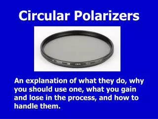
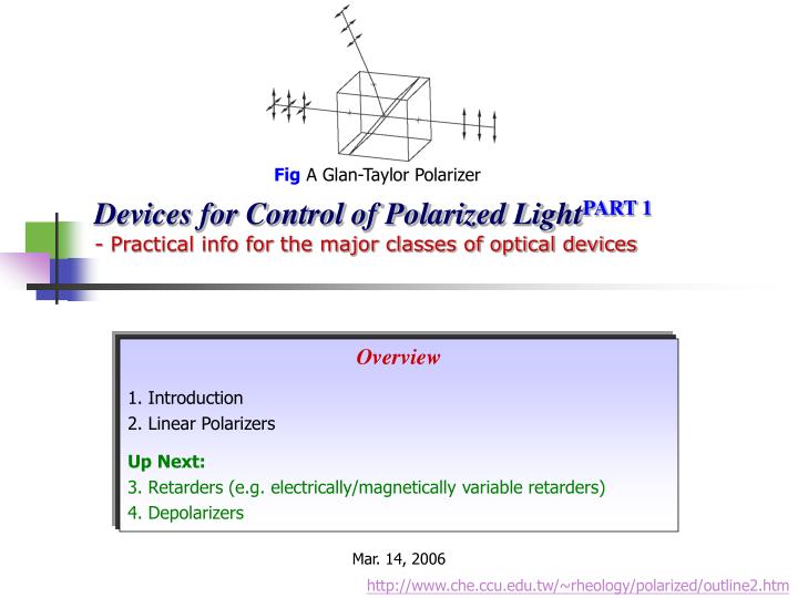
Devices for Control of Polarized Light PART 1 - Practical info for the major classes of optical devices. Fig A Glan-Taylor Polarizer. Overview 1. Introduction 2. Linear Polarizers Up Next: 3. Retarders (e.g. electrically/magnetically variable retarders) 4. Depolarizers. Mar. 14, 2006.

E N D
Devices for Control of Polarized LightPART1- Practical info for the major classes of optical devices Fig A Glan-Taylor Polarizer Overview 1. Introduction 2. Linear Polarizers Up Next: 3. Retarders (e.g. electrically/magnetically variable retarders) 4. Depolarizers Mar. 14, 2006 http://www.che.ccu.edu.tw/~rheology/polarized/outline2.htm
1. Introduction • Factors That Cause the Devices to Deviate from the Ideal: • Absorption of light & Dispersion (change of refractive index with wavelength ) • Geometrical considerations • Angular aperture (limited angular acceptance) Click Here • Spatial aperture (limited beam cross section) • Power handling & Efficiency • Expense • Special peculiarities - Some devices are excessively temperature dependent
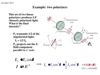
2. Linear Polarizers • General Characteristics • REVIEW OF BASIC OPTICSClick Here • Malus’s law Note: No real pair of polarizers can totally extinguish an incident beam when crossed (i.e., θ= 0) • Extinction ratio
How to measured intensities which differ by several orders of magnitude? ‧ ‧ ‧ ‧ Using a sensitive detector Crossed Parallel
Birefringence Polarizers • In uniaxial crystals, two refractive indices are observed • no is observed for rays polarized perpendicular to the optic axis ordinary rays • ne is observed for rays polarized parallel to the optic axis extraordinary rays O.A. O.A.
The First Type - Producing two beams at a small angle to one another, each of which contains one polarization Normal vector Fig Wollaston prism for negatively birefringent (no>ne) material Fig Rochon prism for negatively birefringent (no>ne) material
REVIEW OF BASIC OPTICSClick Here (全反射) • The Second Type –Over a small range of angles, one polarization undergoes total internal reflection while the other is transmitted Fig Glan-Taylor polarizer for negatively birefringent (no>ne) material cement Fig Glan-Thompson polarizer for negatively birefringent (no>ne) material
Miscellaneous (各式各樣的) Polarizers • Stacked-Plates Polarizer: Plates all tilted at Brewster’s angle • Thin-Film Polarizer: A single plate with a multilayer dielectric coating - Reflected beam: > 99% polarized Transmitted beam: 95% polarized Polarized in the plane of the slide Unpolarized light Polarized out of the plane of the slide
Review of Basic Optics http://www.che.ccu.edu.tw/~rheology/basic_optics/outline.htm (see Chapter 8)
2. Polarizers • Polarizer • Input: Natural light output: Polarized light • Based on one of four fundamental physical mechanisms: a. Dichroism b. Birefringence c. Scattering d. Reflection • It selects a particular polarization state and discards all others (anisotropy in the material of the polarizer) FIG.A linear polarizer and analyzer
Malus’s Law Transmission axis Back FIG. A linear polarizer and analyzer
Review of Basic Optics http://www.che.ccu.edu.tw/~rheology/basic_optics/outline.htm (see Chapter 8)
: dipole • Polarization by Scattering • The dipole does not radiate in the direction of its axis • Increasingly more polarized as the angle increases FIG. Scattering of unpolarized light by a molecule FIG. Scattering of polarized light by a molecule
3. Polarization by Reflection • A Wave Reflecting and Refracting at a Interface Transmission axis is parallel to the ground polarizer perpendicular
electron– oscillator
Contd. 30o 0o 60o 30o 60o The dipole radiation pattern
The reflected beam is strong in P-state light perpendicular to the plane-of-incidence and weak in P-state light parallel to the plane-of-incidence FIG. The pile-of-plates polarizer This plane FIG. The beamsplitter cube Back
Performance of Glan-Taylor prism for rays inside or outside the acceptance angle Incident beam Back
Fig A Glan-Taylor Polarizer Fig A Fresnel rhomb (retarder) Devices for Control of Polarized LightPART 2- Practical info for the major classes of optical devices Overview 3. Retarders 4. Depolarizers Mar. 28, 2006
3. Retarders O.A. (快軸) • Birefringent Materials Isotropic material O.A. e-ray Birefringent material o-ray Anisotropic material (uniaxial) Fig. A half-wave plate showing how a net phase shift accumulates with the retarder
Birefringent Plate Retarders • Linear retarder - introducing a phase difference between two linear polarizations of light • Slow axis ( Fast axis 快軸) - the orientation of the polarization whose phase changes the most within the retarder • a O.A. Fast axis Click here e-ray Slow axis o-ray Anisotropic material (uniaxial)
How a zero-order retarder is made? • Adjustable (multiple order) devices may provide more flexibility ‧ ‧ e-ray o-ray ‧ ‧ ‧ ‧ o-ray e-ray ‧ ‧ Incident light adjustable
y x Quiz: Have you notice that this schematic diagram is plotted incorrectly?
Reflection Retarders • The Fresnel Rhomb linearly polarized Elliptically polarized Circularly polarized Fig. Operation of various reflection retarders
Variable retarders can be divided into two categories • . • Type 1: Mechanically variable retarders • Allowing any particular retardation • Slow time response (1) Soleil-Babinet compensator (2) Photoelastic modulator (PEM) Incident light
Type 2: Electrically Variable Retarders • Applied field • Orient molecules with dipole moments • Optically anisotropic • Macroscopic anisotropy in n Fig. A Kerr cell ‧Response time is only limited by the rotational time constant of the molecules (ps) ‧Polar liquid: Nitrobenzene (硝基苯) ‧W/o alignment difficulties ‧Larger beam cross section Fig. A Pockels cell
4. Depolarizers (偽的) • The depolarizer converts the polarized input into a pseudo-randomly polarized output Fig. A depolarizer
石英 方解石 Back


![Introduction [1/2]](https://cdn1.slideserve.com/3558468/slide1-dt.jpg)