Download
1 / 10
100 likes | 157 Views
Explore the use of a foil-type Gardon gage sensor in the radiant panel test system for heat flux measurement. Learn about calibration, thermal stability, and the correlation between chamber temperature and heat flux. Discover the linear relationship between temperature and heat flux. Gain insights into the characteristics and workings of the circular foil-type Gardon gage heat flux sensor. This study confirms compatibility with the required heat flux value for FAA flammability tests, ensuring accurate and reliable results.

E N D
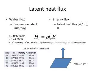
HEAT FLUX MEASUREMENT WITH A FOIL-TYPE GARDON GAGE SENSOR IN THE RADIANT PANEL TEST SYSTEM KHANG D. TRAN, Ph.D. THE MEXMIL COMPANY SANTA ANA, CALIFORNIA, USA International Aircraft Materials Fire Test Working Group Meeting, March 2004, Atlantic City, NJ
FAR 25.856 (a) flammability test requires a heat flux value of 1.5 ± 0.075 Btu/s·ft2 at zero-point location (1.425 - 1.575). Calibration data has been recorded and analyzed to confirm the compatibility of the test system with the allowed 5% tolerance
CALIBRATION CURVE FOR RADIANT PANEL SYSTEM Heat Flux (Btu/s.ft2) Zero Point Position 2 inches Controller Setting Temperature : 1165 °F
CHAMBER TEMPERATURE (F) TIME (s) TEMPERATURE OF RADIANT PANEL CHAMBER AT THE THERMOCOUPLE 1 LOCATION (11 IN., 2 IN., 11.5 IN.)
HEAT FLUX AT ZERO-POINT (BTU/S•FT2) Thermal stability begins TIME (S) HEAT FLUX AT ZERO-POINT LOCATION
CHAMBER TEMPERATURE AND HEAT FLUX CORRELATION Thermal stability
CHAMBER TEMPERATURE AND HEAT FLUX CORRELATION HEAT FLUX AT ZERO-POINT (BTU/S•FT2) (560, 1.5) CHAMBER TEMPERATURE (F) There exists a linear relationship between the chamber temperature (at location of interest (11 in., 2 in., 11.5 in.) and the zero-point heat flux.
THE ZERO-POINT HEAT FLUX VALUE REQUIRED IN FAA 25.856 (a) 1.5 ± 5 % Btu/s·ft2 (or 1.7 ± 5 % Watts/cm2) = (1.425 - 1.575) Btu/s·ft2 or (1.615 - 1.785) Watts/cm2) 558.7 1.452 559.0 1.452 559.0 1.456 559.3 1.458 559.2 1.454 558.9 1.481 559.3 1.465 559.6 1.486 559.6 1.481 559.9 1.481 559.7 1.479 559.8 1.495 560.2 1.456 560.6 1.481 560.8 1.492 561.4 1.492 561.4 1.474 561.7 1.474 561.8 1.479 561.7 1.477 561.8 1.458 562.7 1.456 562.7 1.486 562.0 1.51 DATA IN 24 SEC. DURATION AFTER THERMAL STABILITY BEGINS There is a variation of about 3 °F (0.054%) of the chamber temperature at the location of interest when the heat flux fluctuates in the range of (1.45-1.51) Btu/s·ft2
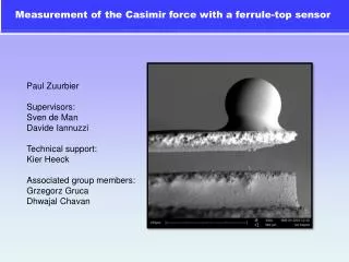
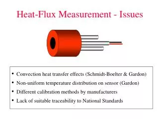
CIRCULAR FOIL-TYPE GARDON GAGE HEAT FLUX SENSOR* To Ts Constantan foil The center to edge temperature difference is proportional to the heat flux Q R2 To - Ts = 4k Copper body Copper wire Besides the heat conduction, both heat convection and heat radiation are present at least to some extent in virtually all cases. The foil-type Gardon gage sensor output is not completely correct because of the distortion of the temperature profile in the foil from the assumed radially symmetric, parabolic profile of heat radiation. E (Voltage output) = thickness of the foil R = active radius of the foil k = thermal conductivity of the material. * T. E. Diller, “Heat Flux”, CRC Press LLC, 2000 and the references cited in this paper


![Heat Flux [Wm -2 ]](https://cdn3.slideserve.com/5899967/heat-flux-wm-2-dt.jpg)