Download

1 / 23
240 likes | 433 Views
HUBS. USB Hub Designs. John Garney Hub Working Group Chair, Intel Corporation Schumann Rafizadeh VP Engineering, Yi Shi Tong. Hub Additions. Requirements and Architecture Additions to USB1.1 Transaction Translator Bulk/Control Transaction Handling

E N D
USB Hub Designs John Garney Hub Working Group Chair, Intel Corporation Schumann Rafizadeh VP Engineering, Yi Shi Tong
Hub Additions • Requirements and Architecture • Additions to USB1.1 • Transaction Translator • Bulk/Control Transaction Handling • Isochronous/Interrupt Transaction Handling • Additions to Chapter 11
Requirements: • Provide high-speed expansion • Isolate full/low-speed from high-speed • Avoid lower speed impact on HS, i.e., LS impact on FS • All USB2.0 Hub Ports support HS/FS/LS • Optional: standardized port indicators (LEDs)
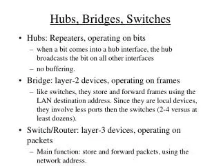
Client Driver Client Driver System SW USB 2.0 Host Controller High Speed Only HS Hub USB 1.1 Device USB 1.1 Hub HS Device (2 x 12Mb/s Capacity) USB 1.1 Device Full/Low Speed Hub In High Speed System • Hub provides high-speed expansion (ala 1.1 hub) • Hub provides additional classic bus(es) • Same total number of devices per USB2.0 Host Controller (e.g. 127) • Greater end user value than classic hub • Performance, expansion and ease of use • Hub is user selected device (not required for all systems)
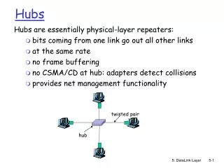
High Speed Only Port HS/Classic Hub Repeater HS/Classic Hub State Machine HS/Classic Hub Controller Port Port Port Hub “Classic Pieces” Reuse Classic Hub Design Knowledge • Repeater • High speed signaling • Also, FS/LS signaling for 1.1 compatibility • Reclocking • State Machine • HS termination sequencing • HS Detect, Reset, Suspend, Resume • Hub Controller • Respond to hub device class requests/events
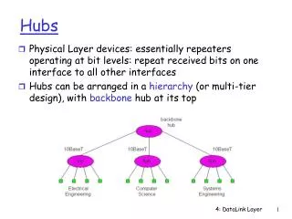
Same as classic hub: High & full/low-speed repeaters, determined by upstream facing link Hub controller No different then classic USB besides high-speed signaling Minor changes from classic hub: Hub state machine (HS detect, HS termination transitions, test mode) New in hub: Transaction Translator Routing logic Hub Architecture High Speed Only Port Transaction Translator HS/Classic Hub Repeater HS/Classic Hub State Machine HS/Classic Hub Controller Full/Low Speed Routing Logic . . . . . Port Port Port
Hub New Pieces High Speed Only Port Transaction Translator Repeater, Controller, ... Full/Low Speed Routing Logic Port Port Port . . . . . • Port Routing Logic • Controllable electrical connection between: • Full/Low (Transaction Translator), or • High-Speed (Repeater) • Route done once per device reset • Transaction Translator • Major addition for USB 2.0 • Uses split transaction protocol HC support
6 - …,ACK 1 – SPLIT-s, OUT, DATAx (Start-split) 5 – SPLIT-c, OUT, … (Complete-split) TT 2 X R 3 - OUT, DATAx, ... 4 - ...,ACK • Host Controller issues start-split transaction to TT • TT buffers full/low speed transaction information (X) locally • TT issues full/low speed transaction on downstream bus • TT buffers full/low speed transaction results (R) locally • TT responds with results • Host Controller issues complete-split transaction to TT Host Controller / TT Interactions Host TT Interrupt Out Example Device
Two separate portions to Transaction Translator Bulk/Control support Interrupt/Isochronous support Bulk/Control uses USB flow control to make progress PING not used Interrupt/Isochronous uses a scheduled full/low speed transaction “pipeline” Separate buffers are used for each TT portion Transaction Translator Bulk & Control Interrupt & Isochronous Transaction Translator Overview
TT buffers 2 or more bulk/control transactions TT issues full/low speed transaction when no periodictransactions pending Host controller issues split transactions to TT Allows starting/completing full/low-speed transactions each microframe Normal approach of “bandwidth reclamation” is used Tries to issue HS start-split; if successful, next attempt does complete-split High Speed Start-/Complete-Split TT Bulk/Ctrl #1 Bulk/Ctrl #2 Full/Low Speed Transaction TT Bulk / Control
Host software budgets when full/low-speed transaction will run Host schedules start-split before “earliest” start time Host schedules complete-split at “latest” finish times Scheduling accounts for variation due to bit-stuffingand timeouts, etc. High Speed Start-Split High Speed Complete-Split TT Start Handler Complete Handler Start-split FIFO Complete-split FIFO Full/Low Handler TT Int. / Isoch. Pipeline
6 - …,ACK 1 – SPLIT-s, OUT, DATAx 5 – SPLIT-c, OUT, ... Start-split FIFO 2 X R 3 - OUT, DATAx, ... 4 - ...,ACK • Host Controller issues start-split transaction to TT • TT buffers full/low speed transaction information locally • TT issues full/low speed transaction on downstream bus • TT buffers full/low speed transaction results locally • Host Controller issues complete-split transaction to TT • TT responds with results Example: Int. OUT Split Trans. TT Start Handler Complete Handler Start-split FIFO Complete-split FIFO Full/Low Handler
Classic Hub + new things Classic Hub - implementation dependent, but knowable baseline New things Signaling Required for any High-Speed device Logic (routing, TT) RAM (buffer space, transaction pipeline) Total (approximate) 40KGates + 1800 Bytes with 4 downstream ports 28KGates + (3KG * # of downstream ports) + 1800 Bytes Port TT FIFOs High-Speed “Classic Hub” TT Logic Routing Logic Port Port Port Hub Cost / Complexity Estimate
USB2.0 HubAdditions Summary • Hub Ports Support all Speeds (High/Full/Low) • Isolation of High and Full/Low Speeds via TT • Simultaneous High and Full/Low-Speed Transactions • Full/Low Speed (12Mb/s) bus per TT • Can be TT per hub or TT per port • TT Internals Overview • Bulk/Control buffering • Interrupt/Isochronous scheduled pipeline
Mega Hub Designs • Architecture • Cascaded Hub Design • Interleaved Hub Design
Mega Hub Designs • Cascaded Mega Hub • Host and Devices use the same TT & Buffers
Mega Hub Designs • Interleaved Mega Hub • Host and Devices use different TT & Buffers
Mega Hub Designs • Advantages of Cascaded Hubs • Ease of design and manufacture • Low Cost • Advantages of Interleaved Hubs • High Performance • Higher Capacity
Flash Storage Strategy • Current off-the-shelf Flash Storage disadvantages; • Lower reliability • Lower capacity • Lower bandwidth • Have lower performance • Advantages; • higher portability • higher availability • lower power consumption • wider applications (mobile phones, cameras, tablets, hand-held gadgets etc.) • Lower cost • The Flash Storage Strategy provides a roadmap of innovations that expand the advantages of Flash Storage devices and eliminate their restrictions and disadvantages. • This roadmap includes, Wear-out detection (Patent xxx), Flash Array (Patent xxx), Flash Hub (Patent xxx) and Flash Cluster.
Flash Storage Strategy - Testing • Device Testing • Flash Array/Flash RAID • HUB • Cluster • Range USB 2.0 & USB 3.0 Testing • Performance Goals • USB 2.0 up to 50 MB/Sec • USB 3.0 up to 500 MB/Sec • Capacity • Dependant on Class and number of mocules
Flash Storage Strategy - Testing Speed USB 3.0 50MB/SEC USB 2.0 Capacity