Download
1 / 44
440 likes | 587 Views
ECE 332 Digital Electronics and Logic Design Lab. Lab 6 Concurrent Statements & Adders. Dataflow VHDL. Major instructions. Concurrent statements. concurrent signal assignment ( ) conditional concurrent signal assignment

E N D
ECE 332Digital Electronics and Logic Design Lab Lab 6 Concurrent Statements & Adders
Dataflow VHDL Major instructions Concurrent statements • concurrent signal assignment () • conditional concurrent signal assignment • (when-else) • selected concurrent signal assignment • (with-select-when) • generate scheme for equations • (for-generate)
Value N … Value N-1 Target Signal Value 2 Value 1 Condition N-1 Condition 2 Condition 1 Conditional concurrent signal assignment When - Else target_signal <= value1whencondition1else value2whencondition2else . . . valueN-1whenconditionN-1else valueN; 0 1 .… 0 1 0 1
Operators • Relational operators • Logic and relational operators precedence = /= < <= > >= Highest not = /= < <= > >= and or nand nor xor xnor Lowest
Priority of Logic and Relational Operators compare a = bc Incorrect … when a = b and c else … equivalent to … when (a = b) and c else … Correct … when a = (b and c) else …
Tri-state Buffer – example ena output input LIBRARY ieee; USE ieee.std_logic_1164.all; ENTITY tri_state IS PORT ( ena: IN STD_LOGIC; input: IN STD_LOGIC_VECTOR(7 downto 0); output: OUT STD_LOGIC_VECTOR (7 DOWNTO 0) ); END tri_state; ARCHITECTURE tri_state_dataflow OF tri_state IS BEGIN output <= input WHEN (ena = '0') ELSE (OTHERS => 'Z'); END tri_state_dataflow; OTHERS means all bits not directly specified,in this case all the bits.
Dataflow VHDL Major instructions Concurrent statements • concurrent signal assignment () • conditional concurrent signal assignment • (when-else) • selected concurrent signal assignment • (with-select-when) • generate scheme for equations • (for-generate)
Selected concurrent signal assignment With –Select-When withchoice_expressionselect target_signal <= expression1whenchoices_1, expression2whenchoices_2, . . . expressionNwhenchoices_N; choices_1 expression1 expression2 choices_2 target_signal expressionN choices_N choice expression
Allowed formats of choices_k WHEN value WHEN value_1 to value_2 WHEN value_1 | value_2 | .... | value N this means boolean “or”
Allowed formats of choice_k - example WITH sel SELECT y <= a WHEN "000", b WHEN "011" to "110", c WHEN "001" | "111", d WHEN OTHERS;
MLU: Entity Declaration LIBRARY ieee; USE ieee.std_logic_1164.all; ENTITY mlu IS PORT( NEG_A : IN STD_LOGIC; NEG_B : IN STD_LOGIC; NEG_Y : IN STD_LOGIC; A : IN STD_LOGIC; B : IN STD_LOGIC; L1 : IN STD_LOGIC; L0 : IN STD_LOGIC; Y : OUT STD_LOGIC ); END mlu;
MLU: Architecture Declarative Section ARCHITECTURE mlu_dataflow OF mlu IS SIGNAL A1 : STD_LOGIC; SIGNAL B1 : STD_LOGIC; SIGNAL Y1 : STD_LOGIC; SIGNAL MUX_0 : STD_LOGIC; SIGNAL MUX_1 : STD_LOGIC; SIGNAL MUX_2 : STD_LOGIC; SIGNAL MUX_3 : STD_LOGIC; SIGNAL L:STD_LOGIC_VECTOR(1 DOWNTO 0);
MLU - Architecture Body BEGIN A1<=NOT A WHEN (NEG_A='1') ELSE A; B1<=NOT B WHEN (NEG_B='1') ELSE B; Y<=NOT Y1 WHEN (NEG_Y='1') ELSE Y1; MUX_0<=A1 AND B1; MUX_1<=A1 OR B1; MUX_2<=A1 XOR B1; MUX_3<=A1 XNOR B1; L <= L1 & L0; with (L) select Y1<=MUX_0 WHEN "00", MUX_1 WHEN "01", MUX_2 WHEN "10", MUX_3 WHEN OTHERS; END mlu_dataflow;
Data-flow VHDL Major instructions Concurrent statements • concurrent signal assignment () • conditional concurrent signal assignment • (when-else) • selected concurrent signal assignment • (with-select-when) • generate scheme for equations • (for-generate)
For Generate Statement For - Generate label:FORidentifier IN rangeGENERATE BEGIN {Concurrent Statements} END GENERATE [label];
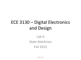
PARITY: Entity Declaration LIBRARYieee; USEieee.std_logic_1164.all; ENTITYparityIS PORT( parity_in : IN STD_LOGIC_VECTOR(7 DOWNTO 0); parity_out : OUT STD_LOGIC ); ENDparity;
xor_out(1) PARITY: Block Diagram xor_out(2) xor_out(3) xor_out(4) xor_out(5) xor_out(6)
PARITY: Architecture ARCHITECTUREparity_dataflowOFparityIS SIGNALxor_out: std_logic_vector (6 downto 1); BEGIN xor_out(1) <= parity_in(0) XORparity_in(1); xor_out(2) <= xor_out(1) XORparity_in(2); xor_out(3) <= xor_out(2) XORparity_in(3); xor_out(4) <= xor_out(3) XORparity_in(4); xor_out(5) <= xor_out(4) XORparity_in(5); xor_out(6) <= xor_out(5) XORparity_in(6); parity_out <= xor_out(6) XORparity_in(7); ENDparity_dataflow;
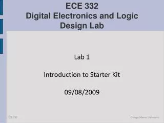
xor_out(1) xor_out(0) PARITY: Block Diagram (2) xor_out(2) xor_out(3) xor_out(4) xor_out(5) xor_out(6) xor_out(7)
PARITY: Architecture ARCHITECTUREparity_dataflowOFparityIS SIGNALxor_out: STD_LOGIC_VECTOR (7 downto 0); BEGIN xor_out(0) <= parity_in(0); xor_out(1) <= xor_out(0) XORparity_in(1); xor_out(2) <= xor_out(1) XORparity_in(2); xor_out(3) <= xor_out(2) XORparity_in(3); xor_out(4) <= xor_out(3) XORparity_in(4); xor_out(5) <= xor_out(4) XORparity_in(5); xor_out(6) <= xor_out(5) XORparity_in(6); xor_out(7) <= xor_out(6) XORparity_in(7); parity_out <= xor_out(7); ENDparity_dataflow;
PARITY: Architecture (2) ARCHITECTUREparity_dataflowOFparityIS SIGNALxor_out: STD_LOGIC_VECTOR (7 DOWNTO 0); BEGIN xor_out(0) <= parity_in(0); G2: FOR i IN1TO7GENERATE xor_out(i) <= xor_out(i-1) XORparity_in(i); END GENERATE; parity_out <= xor_out(7); ENDparity_dataflow;
Simple Rules For combinational logic, use only concurrent statements • concurrent signal assignment () • conditional concurrent signal assignment • (when-else) • selected concurrent signal assignment • (with-select-when) • generate scheme for equations • (for-generate)
Simple Rules • For circuits composed of: • simple logic operations (logic gates) • simple arithmetic operations (addition, subtraction, multiplication) • shifts/rotations by a constant • Use • concurrent signal assignment ()
Simple Rules • For circuits composed of • multiplexers • decoders, encoders • tri-state buffers • Use: • conditional concurrent signal assignment (when-else ) • selected concurrent signal assignment (with-select-when)
Left versus Right Side Left side <= <= when-else with-select <= Right side • Expressions including: • Internal signals (defined • in a given architecture) • Ports of the mode • - in • - inout • - buffer • Internal signals (defined • in a given architecture) • Ports of the mode • - out • - inout • - buffer (don’t recommend • using buffer in this class)
Explicit Component Declaration Tips • For simple projects put entity .vhd files all in same directory • Declare components in main code • Xilinx will figure out hierarchy automatically
METHOD #2: Package component declaration • Components declared in package • Actual instantiations and port maps always in main code
Packages • Instead of declaring all components can declare all components in a PACKAGE, and INCLUDE the package once • This makes the top-level entity code cleaner • It also allows that complete package to be used by another designer • A package can contain • Components • Functions, Procedures • Types, Constants
Package – example (1) LIBRARY ieee ; USE ieee.std_logic_1164.all ; PACKAGE GatesPkg IS COMPONENT mux2to1 PORT (w0, w1, s : IN STD_LOGIC ; f : OUT STD_LOGIC ) ; END COMPONENT ; COMPONENT priority PORT (w : IN STD_LOGIC_VECTOR(3 DOWNTO 0) ; y : OUT STD_LOGIC_VECTOR(1 DOWNTO 0) ; z : OUT STD_LOGIC ) ; END COMPONENT ;
Package – example (2) COMPONENT dec2to4 PORT (w : IN STD_LOGIC_VECTOR(1 DOWNTO 0) ; En : IN STD_LOGIC ; y : OUT STD_LOGIC_VECTOR(0 TO 3) ) ; END COMPONENT ; COMPONENT regn GENERIC ( N : INTEGER := 8 ) ; PORT ( D : IN STD_LOGIC_VECTOR(N-1 DOWNTO 0) ; Enable, Clock : IN STD_LOGIC ; Q : OUT STD_LOGIC_VECTOR(N-1 DOWNTO 0) ) ; END COMPONENT ;
Package – example (3) • constant ADDAB : std_logic_vector(3 downto 0) := "0000"; • constant ADDAM : std_logic_vector(3 downto 0) := "0001"; • constant SUBAB : std_logic_vector(3 downto 0) := "0010"; • constant SUBAM : std_logic_vector(3 downto 0) := "0011"; • constant NOTA : std_logic_vector(3 downto 0) := "0100"; • constant NOTB : std_logic_vector(3 downto 0) := "0101"; • constant NOTM : std_logic_vector(3 downto 0) := "0110"; • constant ANDAB : std_logic_vector(3 downto 0) := "0111"; • END GatesPkg;
Package usage (1) LIBRARY ieee ; USE ieee.std_logic_1164.all ; USE work.GatesPkg.all; ENTITY priority_resolver1 IS PORT (r : IN STD_LOGIC_VECTOR(5 DOWNTO 0) ; s : IN STD_LOGIC_VECTOR(1 DOWNTO 0) ; clk : IN STD_LOGIC; en : IN STD_LOGIC; t : OUT STD_LOGIC_VECTOR(3 DOWNTO 0) ) ; END priority_resolver1; ARCHITECTURE structural OF priority_resolver1 IS SIGNAL p : STD_LOGIC_VECTOR (3 DOWNTO 0) ; SIGNAL q : STD_LOGIC_VECTOR (1 DOWNTO 0) ; SIGNAL z : STD_LOGIC_VECTOR (3 DOWNTO 0) ; SIGNAL ena : STD_LOGIC ;
BEGIN u1: mux2to1PORT MAP ( w0 => r(0) , w1 => r(1), s => s(0), f => p(0)); p(1) <= r(2); p(2) <= r(3); u2: mux2to1PORT MAP ( w0 => r(4) , w1 => r(5), s => s(1), f => p(3)); u3: priority PORT MAP ( w => p, y => q, z => ena); u4: dec2to4PORT MAP ( w => q, En => ena, y => z); u5: regn GENERIC MAP (N => 4) PORT MAP (D => z , Enable => En , Clock => Clk, Q => t ); END structural; Package usage (2)
Explicit Component Declaration versus Package • Explicit component declaration is when you declare components in main code • When have only a few component declarations, this is fine • When have many component declarations, use packages for readability • Packages also help with portability and sharing of libraries among many users in a company • Remember, the actual instantiations always take place in main code • Only the declarations can be in main code or package
How to add binary numbers • Consider adding two 1-bit binary numbers x and y • 0+0 = 0 • 0+1 = 1 • 1+0 = 1 • 1+1 = 10 • Carry is x AND y • Sum is x XOR y • The circuit to compute this is called a half-adder
= s (sum) c (carry)
A full adder is a circuit that accepts as input thee bits x, y, and c, and produces as output the binary sum cs of a, b, and c.
The full adder • The full circuitry of the full adder
Adding bigger binary numbers • We can use a half-adder and full adders to compute the sum of two Boolean numbers 1 0 0 1 1 0 0 + 1 1 1 0 ? 0 1 0
Adding bigger binary numbers • Just chain one half adder and full adders together, e.g., to add x=x3x2x1x0 and y=y3y2y1y0 we need: