Download
1 / 1
10 likes | 180 Views
2D Laser Servoing for Precision Motion Control of an ODV Robotic License Plate Recognition System. Authors: Zhen Song, Kevin Moore, YangQuan Chen, and Vikas Bahl The Center for Self-Organizing and Intelligent Systems (CSOIS) Utah State University, Logan, UT, USA Contact: Dr. Kevin Moore

E N D
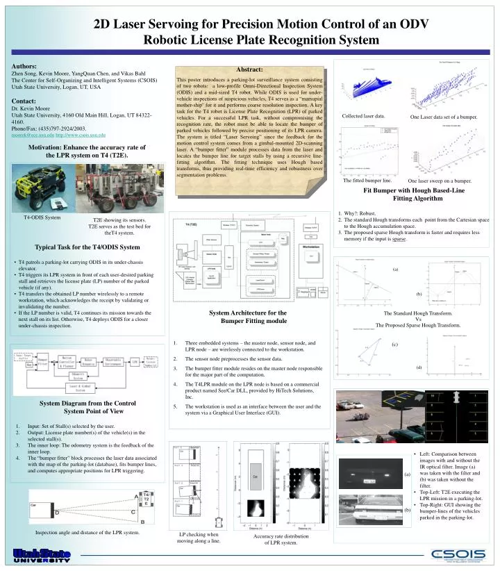
2D Laser Servoing for Precision Motion Control of an ODV Robotic License Plate Recognition System Authors: Zhen Song, Kevin Moore, YangQuan Chen, and Vikas Bahl The Center for Self-Organizing and Intelligent Systems (CSOIS) Utah State University, Logan, UT, USA Contact: Dr. Kevin Moore Utah State University, 4160 Old Main Hill, Logan, UT 84322-4160. Phone/Fax: (435)797-2924/2003. moorek@ece.usu.eduhttp://www.csois.usu.edu Abstract: This poster introduces a parking-lot surveillance system consisting of two robots: a low-profile Omni-Directional Inspection System (ODIS) and a mid-sized T4 robot. While ODIS is used for under-vehicle inspections of suspicious vehicles, T4 serves as a “marsupial mother-ship'' for it and performs coarse resolution inspection. A key task for the T4 robot is License Plate Recognition (LPR) of parked vehicles. For a successful LPR task, without compromising the recognition rate, the robot must be able to locate the bumper of parked vehicles followed by precise positioning of its LPR camera. The system is titled “Laser Servoing” since the feedback for the motion control system comes from a gimbal-mounted 2D-scanning laser. A “bumper fitter” module processes data from the laser and locates the bumper line for target stalls by using a recursive line-fitting algorithm. The fitting technique uses Hough based transforms, thus providing real-time efficiency and robustness over segmentation problems. Collected laser data. One Laser data set of a bumper. Motivation: Enhance the accuracy rate of the LPR system on T4 (T2E). The fitted bumper line. One laser sweep on a bumper. • Fit Bumper with Hough Based-Line Fitting Algorithm • Why?: Robust. • The standard Hough transforms each point from the Cartesian space to the Hough accumulation space. • The proposed sparse Hough transform is faster and requires less memory if the input is sparse. T4-ODIS System T2E showing its sensors. T2E serves as the test bed for theT4 system. • Typical Task for the T4/ODIS System • T4 patrols a parking-lot carrying ODIS in its under-chassis elevator. • T4 triggers its LPR system in front of each user-desired parking stall and retrieves the license plate (LP) number of the parked vehicle (if any). • T4 transfers the obtained LP number wirelessly to a remote workstation, which acknowledges the receipt by validating or invalidating the number. • If the LP number is valid, T4 continues its mission towards the next stall on its list. Otherwise, T4 deploys ODIS for a closer under-chassis inspection. (a) (b) • System Architecture for the Bumper Fitting module • Three embedded systems – the master node, sensor node, and LPR node – are wirelessly connected to the workstation. • The sensor node preprocesses the sensor data. • The bumper fitter module resides on the master node responsible for the major part of the computation. • The T4LPR module on the LPR node is based on a commercial product named See/Car DLL, provided by HiTech Solutions, Inc. • The workstation is used as an interface between the user and the system via a Graphical User Interface (GUI). The Standard Hough Transform. Vs The Proposed Sparse Hough Transform. (c) (d) • System Diagram from the Control System Point of View • Input: Set of Stall(s) selected by the user. • Output: License plate number(s) of the vehicle(s) in the selected stall(s). • The inner loop: The odometry system is the feedback of the inner loop. • The “bumper fitter” block processes the laser data associated with the map of the parking-lot (database), fits bumper lines, and computes appropriate positions for LPR triggering. • Left: Comparison between images with and without the IR optical filter. Image (a) was taken with the filter and (b) was taken without the filter. • Top-Left: T2E executing the LPR mission in a parking-lot. • Top-Right: GUI showing the bumper-lines of the vehicles parked in the parking-lot. (a) (b) Inspection angle and distance of the LPR system. LP checking when moving along a line. Accuracy rate distribution of LPR system.