Download
1 / 1
10 likes | 153 Views
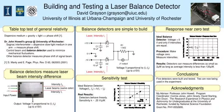
Building and Testing a Laser Balance Detector David Grayson (grayson@uiuc.edu) University of Illinois at Urbana-Champaign and University of Rochester. Table top test of general relativity. Balance detectors are simple to build. Response near zero test.

E N D
Building and Testing a Laser Balance Detector David Grayson(grayson@uiuc.edu) University of Illinois at Urbana-Champaign and University of Rochester Table top test of general relativity Balance detectors are simple to build Response near zero test Dispersive medium + gravity + light => phase shift [1]. Dr. John Howell’s group @ University of Rochester: Sagnac interferometer + dispersive slow-light medium in one arm measure phase shift. Control beam and balance detector used to minimize mechanical fluctuations. Other balance detector measures phase shift of signal beam. [1] S. Manly and E. Page, Phys. Rev. D 63,062003 (2001) Laser, Intensity I1 Ideal Balance Detector: Voltage = 0 if and only if intensities are equal. Procedure: Make voltage zero. Measure intensities. Results: Detectors can measure differences as small as 2µW as long as average intensity is less than 120µW. Voltage V proportional to (I1-I2) (up to ±15V) Balance detectors measure laserbeam intensity difference Laser, Intensity I2 Conclusions Sensitivity test Five detectors were built and tested. Two are now being used in the experiment. Intensity I2 Ideal Balance Detector: Voltage(I1, I2) = k(I1 – I2) Real Results: Detectors behave linearly. Sensitivity k ~ .25 V/µW. Acknowledgments -15 V Laser beams (same color) 0 V +15 V Intensity I1 My Advisor: Professor John Howell. Program Coordinator: Connie Jones, John Gresty, David Starling, Ben Dixon. The Research Experience in Physics and Astronomy for Undergraduates at the University of Rochester, funded by National Science Foundation Grant No. PHY-0552695. Input Power Output: Voltage V proportional to (I1-I2) (up to ±15V)