Download
1 / 76
1.13k likes | 2.21k Views
Laplace Transform Analysis of Signals and Systems. Chapter 10. Transfer Functions. Transfer functions of CT systems can be found from analysis of Differential Equations Block Diagrams Circuit Diagrams. Transfer Functions. A circuit can be described by a system of differential equations.

E N D
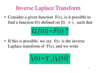
Laplace Transform Analysis of Signals and Systems Chapter 10
Transfer Functions • Transfer functions of CT systems can be found from analysis of • Differential Equations • Block Diagrams • Circuit Diagrams M. J. Roberts - All Rights Reserved. Edited by Dr. Robert Akl
Transfer Functions A circuit can be described by a system of differential equations M. J. Roberts - All Rights Reserved. Edited by Dr. Robert Akl
Transfer Functions Using the Laplace transform, a circuit can be described by a system of algebraic equations M. J. Roberts - All Rights Reserved. Edited by Dr. Robert Akl
Transfer Functions A circuit can even be described by a block diagram. M. J. Roberts - All Rights Reserved. Edited by Dr. Robert Akl
Transfer Functions A mechanical system can be described by a system of differential equations or a system of algebraic equations. M. J. Roberts - All Rights Reserved. Edited by Dr. Robert Akl
Transfer Functions The mechanical system can also be described by a block diagram. Frequency Domain Time Domain M. J. Roberts - All Rights Reserved. Edited by Dr. Robert Akl
System Stability • System stability is very important • A continuous-time LTI system is stable if its impulse response is absolutely integrable • This translates into the frequency domain as the requirement that all the poles of the system transfer function must lie in the open left half-plane of the s plane (pp. 675-676) • “Open left half-plane” means not including the w axis M. J. Roberts - All Rights Reserved. Edited by Dr. Robert Akl
System Interconnections Cascade Parallel M. J. Roberts - All Rights Reserved. Edited by Dr. Robert Akl
System Interconnections Feedback E(s) Error signal Forward path transfer function or the “plant” Feedback path transfer function or the “sensor”. Loop transfer function M. J. Roberts - All Rights Reserved. Edited by Dr. Robert Akl
If K is large enough that then . This means that the overall system is the approximate inverse of the system in the feedback path. This kind of system can be useful for reversing the effects of another system. Analysis of Feedback Systems Beneficial Effects M. J. Roberts - All Rights Reserved. Edited by Dr. Robert Akl
Analysis of Feedback Systems A very important example of feedback systems is an electronic amplifier based on an operational amplifier Let the operational amplifier gain be M. J. Roberts - All Rights Reserved. Edited by Dr. Robert Akl
Analysis of Feedback Systems The amplifier can be modeled as a feedback system with this block diagram. The overall gain can be written as M. J. Roberts - All Rights Reserved. Edited by Dr. Robert Akl
If the operational amplifier low-frequency gain, , is very large (which it usually is) then the overall amplifier gain reduces at low-frequencies to the gain formula based on an ideal operational amplifier. Analysis of Feedback Systems M. J. Roberts - All Rights Reserved. Edited by Dr. Robert Akl
Analysis of Feedback Systems The change in overall system gain is about 0.001% for a change in open-loop gain of a factor of 10. The half-power bandwidth of the operational amplifier itself is 15.9 Hz (100/2p). The half-power bandwidth of the overall amplifer is approximately 14.5 MHz, an increase in bandwidth of a factor of approximately 910,000. M. J. Roberts - All Rights Reserved. Edited by Dr. Robert Akl
Analysis of Feedback Systems Feedback can stabilize an unstable system. Let a forward-path transfer function be This system is unstable because it has a pole in the right half-plane. If we then connect feedback with a transfer function, K, a constant, the overall system gain becomes and, if K > p, the overall system is now stable. M. J. Roberts - All Rights Reserved. Edited by Dr. Robert Akl
Analysis of Feedback Systems Feedback can make an ustable system stable but it can also make a stable system unstable. Even though all the poles of the forward and feedback systems may be in the open left half-plane, the poles of the overall feedback system can be in the right half-plane. A familiar example of this kind of instability caused by feedback is a public address system. If the amplifier gain is set too high the system will go unstable and oscillate, usually with a very annoying high-pitched tone. M. J. Roberts - All Rights Reserved. Edited by Dr. Robert Akl
Analysis of Feedback Systems Public Address System As the amplifier gain is increased, any sound entering the microphone makes a stronger sound from the speaker until, at some gain level, the returned sound from the speaker is a large as the originating sound into the microphone. At that point the system goes unstable (pp. 685-689). M. J. Roberts - All Rights Reserved. Edited by Dr. Robert Akl
Prototype Feedback System Feedback System Without Excitation Analysis of Feedback Systems Stable Oscillation Using Feedback M. J. Roberts - All Rights Reserved. Edited by Dr. Robert Akl
Analysis of Feedback Systems Stable Oscillation Using Feedback Can the response be non-zero when the excitation is zero? Yes, if the overall system gain is infinite. If the system transfer function has a pole pair on the w axis, then it is infinite at the frequency of that pole pair and there can be a response without an excitation. In practical terms the trick is to be sure the poles stay on the w axis. If the poles move into the left half-plane the response attenuates with time. If the poles move into the right half-plane the response grows with time (until the system goes non-linear). M. J. Roberts - All Rights Reserved. Edited by Dr. Robert Akl
Analysis of Feedback Systems Stable Oscillation Using Feedback A real example of a system that oscillates stably is a laser. In a laser the forward path is an optical amplifier. The feedback action is provided by putting mirrors at each end of the optical amplifier. M. J. Roberts - All Rights Reserved. Edited by Dr. Robert Akl
Analysis of Feedback Systems Stable Oscillation Using Feedback Laser action begins when a photon is spontaneously emitted from the pumped medium in a direction normal to the mirrors. M. J. Roberts - All Rights Reserved. Edited by Dr. Robert Akl
Analysis of Feedback Systems Stable Oscillation Using Feedback If the “round-trip” gain of the combination of pumped laser medium and mirrors is unity, sustained oscillation of light will occur. For that to occur the wavelength of the light must fit into the distance between mirrors an integer number of times. M. J. Roberts - All Rights Reserved. Edited by Dr. Robert Akl
Analysis of Feedback Systems Stable Oscillation Using Feedback A laser can be modeled by a block diagram in which the K’s represent the gain of the pumped medium or the reflection or transmission coefficient at a mirror, L is the distance between mirrors and c is the speed of light. M. J. Roberts - All Rights Reserved. Edited by Dr. Robert Akl
Analysis of Feedback Systems The Routh-Hurwitz Stability Test The Routh-Hurwitz Stability Test is a method for determing the stability of a system if its transfer function is expressed as a ration of polynomials in s. Let the numerator be N(s) and let the denominator be M. J. Roberts - All Rights Reserved. Edited by Dr. Robert Akl
D even D odd Analysis of Feedback Systems The Routh-Hurwitz Stability Test The first step is to construct the “Routh array”. M. J. Roberts - All Rights Reserved. Edited by Dr. Robert Akl
Analysis of Feedback Systems The Routh-Hurwitz Stability Test The first two rows contain the coefficients of the denominator polynomial. The entries in the following row are found by the formulas, ... The entries on succeeding rows are computed by the same process based on previous row entries. If there are any zeros or sign changes in the column, the system is unstable. The number of sign changes in the column is the number of poles in the right half-plane (pp. 693-694). M. J. Roberts - All Rights Reserved. Edited by Dr. Robert Akl
Analysis of Feedback Systems Root Locus Common Type of Feedback System System Transfer Function Loop Transfer Function M. J. Roberts - All Rights Reserved. Edited by Dr. Robert Akl
Analysis of Feedback Systems Root Locus Poles of H(s) Zeros of 1 + T(s) T is of the form Poles of H(s) Zeros of 1 + Poles of H(s) or M. J. Roberts - All Rights Reserved. Edited by Dr. Robert Akl
Analysis of Feedback Systems Root Locus K can range from zero to infinity. For K approaching zero, using the poles of H are the same as the zeros of which are the poles of T. For K approaching infinity, using the poles of H are the same as the zeros of which are the zeros of T. So the poles of H start on the poles of T and terminate on the zeros of T, some of which may be at infinity. The curves traced by these pole locations as K is varied are called the root locus. M. J. Roberts - All Rights Reserved. Edited by Dr. Robert Akl
Let and let . Then No matter how large K gets this system is stable because the poles always lie in the left half-plane. Root Locus Analysis of Feedback Systems Root Locus M. J. Roberts - All Rights Reserved. Edited by Dr. Robert Akl
Let and let . At some finite value of K the system becomes unstable because two poles move into the right half-plane. Root Locus Analysis of Feedback Systems Root Locus M. J. Roberts - All Rights Reserved. Edited by Dr. Robert Akl
Analysis of Feedback Systems Root Locus Four Rules for Drawing a Root Locus 1. Each root-locus branch begins on a pole of T and terminates on a zero of T. 2. Any portion of the real axis for which the sum of the number of real poles and/or real zeros lying to its right is odd, is a part of the root locus. 3. The root locus is symmetrical about the real axis. . . M. J. Roberts - All Rights Reserved. Edited by Dr. Robert Akl
Analysis of Feedback Systems Root Locus . . 4. If the number of poles of T exceeds the number of zeros of T by an integer, m, then m branches of the root locus terminate on zeros of T which lie at infinity. Each of these branches approaches a straight-line asymptote and the angles of these asymptotes are at the angles, with respect to the positive real axis. These asymptotes intersect on the real axis at the location, M. J. Roberts - All Rights Reserved. Edited by Dr. Robert Akl
Analysis of Feedback Systems Root Locus Examples M. J. Roberts - All Rights Reserved. Edited by Dr. Robert Akl
Analysis of Feedback Systems Gain and Phase Margin Real systems are usually designed with a margin of error to allow for small parameter variations and still be stable. That “margin” can be viewed as a gain margin or a phase margin. System instability occurs if, for any real w, a number with a magnitude of one and a phase of -p radians. M. J. Roberts - All Rights Reserved. Edited by Dr. Robert Akl
Analysis of Feedback Systems Gain and Phase Margin So to be guaranteed stable, a system must have a T whose magnitude, as a function of frequency, is less than one when the phase hits -p or, seen another way, T must have a phase, as a function of frequency, more positive than - p for all |T| greater than one. The difference between the a magnitude of T of 0 dB and the magnitude of T when the phase hits - p is the gain margin. The difference between the phase of T when the magnitude hits 0 dB and a phase of - p is the phase margin. M. J. Roberts - All Rights Reserved. Edited by Dr. Robert Akl
Analysis of Feedback Systems Gain and Phase Margin M. J. Roberts - All Rights Reserved. Edited by Dr. Robert Akl
Analysis of Feedback Systems Steady-State Tracking Errors in Unity-Gain Feedback Systems A very common type of feedback system is the unity-gain feedback connection. The aim of this type of system is to make the response “track” the excitation. When the error signal is zero, the excitation and response are equal. M. J. Roberts - All Rights Reserved. Edited by Dr. Robert Akl
Analysis of Feedback Systems Steady-State Tracking Errors in Unity-Gain Feedback Systems The Laplace transform of the error signal is The steady-state value of this signal is (using the final-value theorem) If the excitation is the unit step, , then the steady- state error is M. J. Roberts - All Rights Reserved. Edited by Dr. Robert Akl
Analysis of Feedback Systems Steady-State Tracking Errors in Unity-Gain Feedback Systems If the forward transfer function is in the common form, then If and the steady-state error is zero and the forward transfer function can be written as which has a pole at s = 0. M. J. Roberts - All Rights Reserved. Edited by Dr. Robert Akl
Analysis of Feedback Systems Steady-State Tracking Errors in Unity-Gain Feedback Systems If the forward transfer function of a unity-gain feedback system has a pole at zero and the system is stable, the steady-state error with step excitation is zero. This type of system is called a “type 1” system (one pole at s = 0 in the forward transfer function). If there are no poles at s = 0, it is called a “type 0” system and the steady-state error with step excitation is non-zero. M. J. Roberts - All Rights Reserved. Edited by Dr. Robert Akl
Analysis of Feedback Systems Steady-State Tracking Errors in Unity-Gain Feedback Systems The steady-state error with ramp excitation is Infinite for a stable type 0 system Finite and non-zero for a stable type 1 system Zero for a stable type 2 system (2 poles at s = 0 in the forward transfer function) M. J. Roberts - All Rights Reserved. Edited by Dr. Robert Akl
Block Diagram Reduction It is possible, by a series of operations, to reduce a complicated block diagram down to a single block. Moving a Pick-Off Point M. J. Roberts - All Rights Reserved. Edited by Dr. Robert Akl
Block Diagram Reduction Moving a Summer M. J. Roberts - All Rights Reserved. Edited by Dr. Robert Akl
Block Diagram Reduction Combining Two Summers M. J. Roberts - All Rights Reserved. Edited by Dr. Robert Akl
Block Diagram Reduction Move Pick-Off Point M. J. Roberts - All Rights Reserved. Edited by Dr. Robert Akl
Block Diagram Reduction Move Summer M. J. Roberts - All Rights Reserved. Edited by Dr. Robert Akl
Block Diagram Reduction Combine Summers M. J. Roberts - All Rights Reserved. Edited by Dr. Robert Akl
Block Diagram Reduction Combine Parallel Blocks M. J. Roberts - All Rights Reserved. Edited by Dr. Robert Akl