Download
1 / 25
260 likes | 477 Views
Low-Power Dynamic Voltage Scaling System. Taeg Sang Cho, Ravi Palakodety, Anantha Chandrakasan Massachusetts Institute of Technology. Outline. Introduction Speed Detector with Adaptive Delay Scheme Test Vector Generator PWM Control and Buck Converter Conclusion. Why Low Power?.

E N D
Low-Power Dynamic Voltage Scaling System Taeg Sang Cho, Ravi Palakodety, Anantha Chandrakasan Massachusetts Institute of Technology
Outline • Introduction • Speed Detector with Adaptive Delay Scheme • Test Vector Generator • PWM Control and Buck Converter • Conclusion
How does the power numbers look? Courtesy of Wikipedia
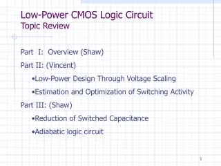
Possible Optimization Space • Software • Simple Program Code (algorithm) • Efficient Compiler Technology • Hardware • Efficient Circuit Synthesis Tools • Low Power Circuit Techniques
Key Metric: Energy per Operation Off-current Delay per operation Switched capacitance Metric of Interest Lowering VDD will reduce the energy per operation, but will increase the delay per operation, thus incursa reliability penalty!
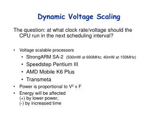
D Q D Q Dynamic Voltage Scaling (DVS) VDD = 1.2V LOGIC CLK
D Q D Q Dynamic Voltage Scaling (DVS) VDD = 0.3V LOGIC CLK Functionality Error!
Dynamic Voltage Scaling • For fixed throughput applications, minimize energy/sample in circuits. • Adjust the power supply voltage to finish critical circuit operations “just-in-time”.
System Block Diagram 1.2 V VDD Power Supply(DC-DC Conv) Circuit of Interest Speed Detector(Critical Path replica) System of interest in this presentation
Challenges of DVS • Highly efficient DC-DC converter • Low Overhead DVS control • Ensure that replica tracks real critical path in light of Threshold Voltage variations
Outline • Introduction • Speed Detector with Adaptive Delay Scheme • Test Vector Generator • PWM Control and Buck Converter • Conclusion
Delay Variation in advanced CMOS In 65nm CMOS Processes, the delay variation in circuits poses an challenge
Adaptive Delay Scheme Run at startup to match delay of replica and real path
Outline • Introduction • Speed Detector with Adaptive Delay Scheme • Test Vector Generator • PWM Control and Buck Converter • Conclusion
New Test-Vector Generator • We have a 50kHz clock for Accumulator!
Simulation Result • Power Dissipation = 546 nW • at FEXT=25MHz • Vector generator in Kuroda’s Paper • (JSSC 1998) • Power Dissipation = 2.72uW • at FEXT= 25MHz • (Simulated at 65nm process node)
Outline • Introduction • Speed Detector with Adaptive Delay Scheme • Test Vector Generator • PWM Control and Buck Converter • Conclusion
Conclusion • Contribution • Implementation of Energy Efficient DVS System for Low-Power Applications : 6.4X Improvements in Power Compared with Similar Type Systems • Future work • Improvement in Loop Transient Response • Reduction in DLL Power Consumption • Continuous Adaptive-delay Element (e.g. DLL)
Reference [1] Variable Supply-Voltage Scheme for Low-Power High-Speed CMOS Digital Design Kuroda et al. IEEE JSSC 1998 [2] High-Efficiency Multiple-Output DC-DC Conversion for Low-Voltage Systems Dancy et al. IEEE. Trans VLSI 2000