Download
1 / 101
1.02k likes | 1.2k Views
ITEC4610 Network Switching and Routing. ดร. ประวิทย์ ชุมชู หัวหน้าสาขาวิชาวิศวกรรมสารสนเทศและการสื่อสาร (ICE) MUT Email: prawit@mut.ac.th ห้องทำงาน : F402 เบอร์โทรศัพท์ที่ทำงาน : (02)9883655 ต่อ 220 เบอร์โทรศัพท์เคลื่อนที่ : 065343850. Class IV Ethernet and VLAN. ดร. ประวิทย์ ชุมชู

E N D
ITEC4610Network Switching and Routing ดร. ประวิทย์ ชุมชู หัวหน้าสาขาวิชาวิศวกรรมสารสนเทศและการสื่อสาร(ICE) MUT Email: prawit@mut.ac.th ห้องทำงาน: F402 เบอร์โทรศัพท์ที่ทำงาน: (02)9883655 ต่อ 220 เบอร์โทรศัพท์เคลื่อนที่: 065343850
Class IVEthernet and VLAN ดร. ประวิทย์ ชุมชู หัวหน้าสาขาวิชาวิศวกรรมสารสนเทศและการสื่อสาร(ICE) MUT Email: prawit@mut.ac.th ห้องทำงาน: F402 เบอร์โทรศัพท์ที่ทำงาน: (02)9883655 ต่อ 220 เบอร์โทรศัพท์เคลื่อนที่: 065343850
หัวข้อที่จะบรรยาย • พื้นฐานการเข้าถึงช่องสัญญาณ (Medium Access Control) • พื้นฐานการทำงานของ Ethernet • พื้นฐานการทำงานของ Spanning Tree Protocols • พื้นฐานการทำงานของ Virtual LAN (VLAN) • พื้นฐานการทำงานของ VLAN trucking Protocol (VTP)
พื้นฐานการเข้าถึงช่องสัญญาณ(Medium Access Control) • Point-to-Point • Sharing • Algorithms: • TDMA(Time Division Multiple Access) • FDMA(Frequency Division Multiple Access) • CDMA(Code Division Multiple Access) • ALOHA • CSMA/CD (Carrier Sense Multiple Access / Collision Detection) • CSMA/CA (Carrier Sense Multiple Access / Collision Avoidance) • Protocols: • Ethernet • Token Ring • FDDI • 802.11 WLAN
ประเภทการสื่อสาร • Half Simplex • Half-Duplex • Full-Duplex
ประเภทการเข้าถึงช่องสัญญาณประเภทการเข้าถึงช่องสัญญาณ • TDMA (Time Division Multiple Access) • FDMA (Frequency Division Multiple Access) • CDMA (Code Division Multiple Access)
TDMA (Time Division Multiple Access) • Aloha • CSMA/CD (Carrier Sense Multiple Access / Collision Detection) • CSMA/CA (Carrier Sense Multiple Access / Collision Avoidance) • Etc.
TDMA TDMA: time division multiple access • access to channel in "rounds" • each station gets fixed length slot (length = pkt trans time) in each round • unused slots go idle • example: 6-station LAN, 1,3,4 have pkt, slots 2,5,6 idle
FDMA (Frequency Division Multiple Access) - channel spectrum divided into frequency bands - each station assigned fixed frequency band - unused transmission time in frequency bands go idle
CDMA (Code Division Multiple Access) • WCDMA (Wide Band CDMA)
CDMA • unique “code” assigned to each user; ie, code set partitioning • used mostly in wireless broadcast channels (cellular, satellite, etc) • all users share same frequency, but each user has own “chipping” sequence (ie, code) to encode data • encoded signal = (original data) X (chipping sequence) • decoding: inner-product of encoded signal and chipping sequence • allows multiple users to “coexist” and transmit simultaneously with minimal interference (if codes are “orthogonal”)
Aloha • Random schemes, simple. • Good for initial call setup. • Channel efficiency only 18% for Aloha, 36% for Slotted Aloha (assuming Poisson distribution for packet arrival and packet length) • No delay guarantee.
CSMA • Non-persistent CSMA: stations sense the carrierand start sending immediately if the medium isidle; otherwise wait for a random amount of timeand retry. • P-persistent CSMA: sense the carrier and if idle,only transmit with probability p; defer to the nextslot with probability 1-p. • 1-persistent CSMA: many stations listen andtransmit at the same time which causescollisions.
CSMA/CD • Non-persistent CSMA: stations sense the carrierand start sending immediately if the medium isidle; otherwise wait for a random amount of time(K) and retry. • Exponential Backoff: • 1st collision: choose K randomly from [0, T]. • 2nd collision: choose K randomly from [0, 2T].
CSMA/CD Backoff Algorithm transmission aborted Backoff Time (# slot times) backoff truncated 10 2 - 1 9 2 - 1 8 2 - 1 7 2 - 1 6 2 - 1 binary exponential backoff algorithm 5 2 - 1 4 2 - 1 3 2 - 1 2 2 - 1 1 2 - 1 0 1 2 3 4 5 6 7 8 9 10 11 12 13 14 15 16 # Transmission Attempts
หัวข้อที่จะบรรยาย • พื้นฐานการเข้าถึงช่องสัญญาณ (Medium Access Control) • พื้นฐานการทำงานของ Ethernet • พื้นฐานการทำงานของ Spanning Tree Protocols • พื้นฐานการทำงานของ Virtual LAN (VLAN) • พื้นฐานการทำงานของ VLAN trucking Protocol (VTP)
Ethernet Roadmap 1976 originated as Alohanet 1980 industry standards initiatives 1982 Thick Coax deployment started 1984 Thin Coax products emerge 1988 1Mbit/s Starlan became popular 1990 10BASE-T Twisted-Pair took over 1991 Switched Ethernet products 1992 100Mbit/s Ethernet initiatives 1995 Gigabit Ethernet work started 1999 10Gbit/s Ethernet proposed
Ethernet Standards Name Medium Standard 1BASE 5 Twisted Pair ISO/IEC 8802-3 (1996) 10BASE 5 Thick Coax ISO/IEC 8802-3 (1996) 10BASE 2 Thin Coax ISO/IEC 8802-3 (1996) 10BASE-F Optical Fibre ISO/IEC 8802-3 (1996) 10BASE-T Twisted Pair ISO/IEC 8802-3 (1996) 100BASE-F Optical Fibre IEEE 802-3u (1995) 100BASE-T Twisted Pair IEEE 802-3u (1995) Full Duplex - IEEE 802-3x (1997) 1000BASE-F Optical Fibre IEEE 802-3z (1998) 1000BASE-T Twisted Pair IEEE 802-3ab (1999) VLAN Tagging - IEEE 802.3ac (1998) Link Aggregation Optical Fibre IEEE 802.3ad (2000) 10GBASE-F Optical Fibre IEEE 802.3ae (2002) Remote Powering Twisted Pair IEEE 802.3af (2002) 10GBASE-T Twisted Pair IEEE 802.3an (2006)
10 Mbit/s Half-Duplex Ethernet Performance Utilisation Breakdown Danger Safe Frame Size (Octets) Source: ICL Tech.J Nov 1986
Naming - ใช้ในการจัดส่ง การรับเฟรมภายในเครือข่าย - Physical Address
CSMA/CD Collision Domain last-minute collision CSMA/CD Frame = 512 bits min Collision Signal slot time = 51.2us @ 10 Mbit/s (approx 3-4km cable)
Types of Collisions • Local collision • Remote Collision • Late Collision
Types of Collisions Local Collision Remote Collision Late Collision
Frame Reception • Frame reception is essentially the same for both half-duplex and full-duplex operations, except that full-duplex MACs must have separate frame buffers and data paths to allow for simultaneous frame transmission and reception. • The destination address of the received frame is checked and matched against the station's address list (its MAC address, its group addresses, and the broadcast address) to determine whether the frame is destined for that station. • If an address match is found, the frame length is checked and the received FCS is compared to the FCS that was generated during frame reception. If the frame length is okay and there is an FCS match, the frame type is determined by the contents of the Length/Type field. The frame is then parsed and forwarded to the appropriate upper layer.
Remote Power via Modular Connector Spare Pair Powering = Pins 4,5 and 7,8 (used for mid-span powering by 10/100) Signal Pair Powering = Pins 1,2 and 3,6 Power Supply Equipment (PSE) Powered Device (PD) hub/switch integral or mid-span transmit signal from PD transmit pair power supply Load receive signal to PD receive pair
Remotely Powered Ethernet Supported • 10BASE-T 10Mbs 2-pair Cat 3 • 100BASE-TX 100Mbs 2-pair Cat 5 • 1000BASE-T 1000Mbs 4-pair Cat 5
Remote Power Classifications Class Usage Power levels Power levels at PSE output at PD input 0 Default 0.50w - 15.00w 0.44w - 12.95w 1 Optional 0.50w - 4.00w 0.44w - 3.84w 2 Optional 4.00w - 7.00w 3.84w - 4.69w 3 Optional 7.00w - 15.00w 6.49w - 12.95w 4 Reserved 0.50w - 15.00w Reserved 5 Reserved 0.50w - 15.00w Reserved
หัวข้อที่จะบรรยาย • พื้นฐานการเข้าถึงช่องสัญญาณ (Medium Access Control) • พื้นฐานการทำงานของ Ethernet • พื้นฐานการทำงานของ Spanning Tree Protocols • พื้นฐานการทำงานของ Virtual LAN (VLAN) • พื้นฐานการทำงานของ VLAN trucking Protocol (VTP)
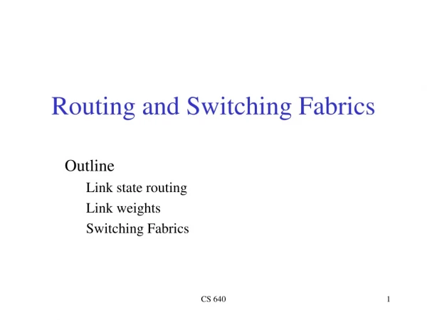
Objectives • Redundant topologies • SpanningTree Protocol
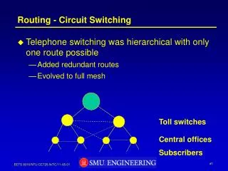
Redundancy Redundant networking topologies are designed to ensure that networks continue to function in the presence of single points of failure.
Redundant Topologies • A goal of redundant topologies is to eliminate network outages caused by a single point of failure. • All networks need redundancy for enhanced reliability.