Download
1 / 37
380 likes | 658 Views
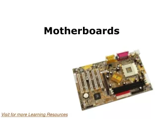
Motherboards. Chapter 3. Motherboards. Motherboard is considered the most important element of a computer’s design Provides a physical surface on which to mount electronic components such as resistors, capacitors, chips, slots and sockets

E N D
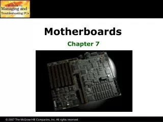
Motherboards Chapter 3
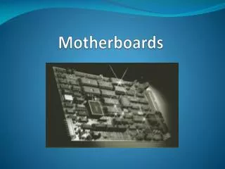
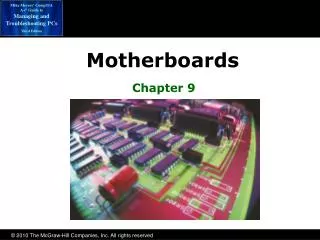
Motherboards • Motherboard is considered the most important element of a computer’s design • Provides a physical surface on which to mount electronic components such as resistors, capacitors, chips, slots and sockets • Provides a means for expanding and customizing they system by inserting expansion boards into slots • Also referred to as the system board, main board, and planar board
Motherboards (cont’d) • The electrical circuits that run across the surface of the motherboard are called traces • A collection of traces and conductors is called a bus. There are many types of busses • Data bus (Buss width of 8,16,32, and64 bit buss) • Control bus – activates devices i.e. hard drive • Power bus – sends electrical power to low consumption devices • Internal bus – integrated circuit inside CPU • Memory bus – connect CPU to RAM • I/O bus (expansion buss) CPU to expansion slots
Motherboards (cont’d) • A collection of busses is also called a bus • The Local bus consists of the power bus, data bus, control bus, and the memory bus • Local bus is also called memory bus, system bus or front side bus (FSB) • The back side bus describes the CPU internal bus
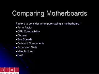
Form Factors • Form factor: (footprint) The physical shape or outline of the motherboard • Must be considered when upgrading a PC • Power supply must match the motherboard • XT, AT and Baby AT • XT Original IBM PC (1983) 8-bit • AT slightly larger than XT 16-bit • Baby AT same size as XT but 16-bit
Form Factors (cont’d) • ATX (popular until 1996) • Most common form factor for full-size computers • Looks like Baby ATX turned 90 degree • Polarized power supply connector* • Requires special shaped power supply • Three common sizes • ATX – 12.0” x 9.6” • Micro ATX – 9.6” x 9.6” • Flex ATX – 7.5” x 9.6”
Form Factors (cont’d) • Mini ITX: Smaller version of the micro ATX • Used for small desktop computers and mobile devices • Mini ITX - 6.7” x 6.7” • Nano ITX - 4.7” x 4.7” • Pico ITX - 3.94” x 2.83” • Mobile ITX - 2.36” x 2.36”
Form Factors (cont’d) • LPX designed for low profile desktop or slim towers • Does not have expansion slots • Single expansion slot mounted in the center of the board • Single slot host a bus riser card • Popular in low priced computers • Not standard, proprietary center slot is not always is same place
Form Factors (cont’d) • NLX Uses a bus riser card but it is located at the end of the board (the edge of the board actually plugs into the riser card) • Standardized • Sized 9.0” x 10”-13.6” • Used in Gateway, HP, IBM,NEC and Micron • BTX Designed to help cool CPU by placing it right by fan • Reduced Number of Fans and noise • Obsolete case • BTX 10.5 x 12.8 • Micro BTX 10.5 x 10.4 • Nano BTX 10.5 x 8.8 • Pico BTX 10.5 x 8.0
Form Factors (cont’d) • Backplane: a circuit board with an abundance of slots along the length of the board. • Not a true form factor • Used in heavy industry • There are two types of Backplanes: • Passive: all typical motherboard circuits and chips are located on the expansion boards • Active: contains the usual circuits and chips normally found on a motherboard
Bus System Architecture • Originally computers had one bus. It ran at same speed as the CPU • As CPU speeds increased high speed frequency increase inductive reactance occurred with in the bus system. • Inductive reactance magnetic or radio interference actually chokes electron flow. • Twisted pairs counteracts IR • Length of wires actually affect data transfer speed
Bus System Architecture • Chipsets manage buses of different frequencies • Originally two chipsets were used: • North chipset close to CPU connect high speed devices to CPU (called north bridge) • South chipset connect low speed devices (south bridge) • Intel phased out North and south bridge and replaced it with Quick Path Interconnect (QPI) • AMD phased out and replaced it with HyperTransport Technologies
Bus System Architecture (cont’d) • Without chipsets the CPU would be required to handle all computer data transfers thus slowing is down. • Chipsets enable expansion slots • Chipsets are an integral part of the motherboard and are not field replaceable. • If a chipset the entire motherboard must be replaced
Expansion Card Slots • Expansion card slots provide a quick and easy method of connecting devices directly to the motherboard by accepting adapters, expansion cards, interface cards, and daughter boards • Most common expansion slots are PCI Express • USB and IEEE-1394 (firewire) not true slots but act like one
Expansion Card Slots (cont’d) • Peripheral Components Interconnect (PCI) • 32 Bit • 66 MHz • 132 MBps • PCI-X • 64 Bit • 266 MHz • 17 Gbps • PCI Express (PCI-E) • 64 Bit • 533 MHZ • 34 Gbps • Serial
Expansion Card Slots (cont’d) • MiniPCI and MiniPCIe: smaller versions of full size PCI and PCIe designed for laptops, notebooks and other portable devices • IEEE-1394 (Firewire): like USB eliminate the need for expansion slots, parallel ports and serial ports. • USB is pushing it out of the market • Can be added with an expansion card.
Expansion Card Slots (cont’d) • Universal Service Bus (USB) designed to replace any expansion slot except high data rate video expansion slot. • Allows addition of devices without opening case • Can support 127 devices • Plug and play • Devices take turns communicating through USB port, sending ‘packets’ of data like a network • USB 2.0 - 480 Mbps (data one way at a time - half duplex) • USB 3.0 - 5 Gbps(data flow both ways at one – full duplex)
Expansion Card Slots (cont’d) USB Cables: • USB 2.0 4 wires: • 2 data (twisted pair) • 2 Power • USB 3.0 10 wires: • 2 USB 2.0 data (twisted pair) • 2 USB 3.0 data receive (twisted pair) • 2 USB 3.0 data transmit (twisted pair) • 1 5 volts (+) • 1 power ground (-) • 1 electrical ground for signal (-) • 1 electrical ground for shielding (-)
Expansion Card Slots (cont’d) • USB ports often identified with a blue connector • Upgrading to USB 3.0 • Install expansion card to PCIe slot • Install drivers • Accelerated Graphics Port (AGP) Designed exclusively for video card • Located close to RAM and CPU • DIME direct Memory Execute • Almost obsolete
Expansion Card Slots (cont’d) • By combining the functions of several separate technologies into one unit a more economical device can be produced: • AMR - Audio/Modem riser • ACR - Advanced Communication riser • CNR - Communication and Network riser • Combine NIC, modem, audio, USB and DSI cards
System Resources • Device Manager: Assigns and allocates system resources • Access device manager by typing “device manager” into search box • Lists hardware devices installed in system • Properties tab list information about hardware configuration and resources • Can view/update/roll back/uninstall drivers,
System Resources (cont’d) • Search System Information in search box • Select system summary • Operating system and version • Computer name • User name • Processor type • BIOS version • I/O Port and memory address • Memory address range: assigned section of memory used as temporary data storage • I/O Port address is assigned for identification
System Resources (cont’d) • Interrupt Request (IQR): literally interrupt as processes taking place in the CPU to give attention to some device such as the keyboard • IQR are numbered 0-15 • Lower number = higher priority • Two IRQ assignments can be shared if devices are not used at same time (scanner and camera) • IF two devices with same IQR try to access CPU at same time system locks up • Hardware and software IQR exist
System Resources (cont’d) • Direct Memory Access (DMA) a combination of hardware and software that allows then hard drive to directly transfer data to memory without involving the CPU • DMA controller is a chip that controls the DMA channels • Bus Mastering takes control of the busses involved in DMA and allows devices to carryout tasks with without involving CPU
System Resources (cont’d) • Plug and Play: automatic assignments of system resources • Simply plug the device in and the computer configures it • Before Plug and Play techs needed to • Set jumpers • Set dip switches • Load drivers
Installing Software Drivers • Install drivers before installing hardware • Avoids O/S from selecting a generic driver which may not work • Drivers are usually supplied on a CD/DVD with the hardware • Device driver has rollback and update driver options • Motherboard chipsets also have drivers • Use custom install –choose exactly what software you want • Default install will load lots of extra/unwanted software
Upgrading BIOS • Upgrading BIOS common when upgrading hardware in older systems • To Upgrade BIOS • Older systems required new chip • EPROM: Remove foil label and shine ultraviolet light into hole under label to erase chip then reprogram • EEPROM (Flash BIOS) easily erased electronically then updated using software from the motherboard manufacturer’s website
Upgrading BIOS (cont’d) General instructions for upgrading flash BIOS • Download new BIOS from website • Copy BIOS onto Flash drive • Boot PC with flash drive inserted • Run BIOS upgrade program • When asked, type exact name of BIOS file • IF asked if you want to backup existing BIOS – YES • When procedure is complete REBOOT PC • Enter setup utility and set it to its default settings • Save changes and REBOOT • During reboot enter SETUP and correct date/time/settings • Save changes and reboot one more time
Upgrading BIOS (cont’d) • Alternate BIOS upgrade (if equipped) • USB Flashback button found on back of motherboard • Insert USB flash drive with new BIOS into white USB 2.0 • Press button • BI(OS firmware is automatically updated!
Setup Utility • Setup utility allows you to • Identify type of hard drive • Identify chipset • Set password for setup utility • Select power management features • Configure boot order • Setup utility is activated by a special set of keystrokes displayed during startup (or check motherboard manufacturer’s website) • Move jumper to “clear CMOS” and back to clear P/W*
Troubleshooting Motherboards • Motherboard manufacturer include drawings of motherboards with component locations in user guides and websites • Motherboard is one of the most expensive parts to replace • Trouble shooting may require third party diagnostic software or hardware • First trouble shoot failed hardware to ensure it is not the problem (i.e. modem not working)
Troubleshooting Motherboards • Check for loose connections unplug and plug connections and jumpers • Remove and reinstall the CPU • Check for signs of high voltage damage • If problem disappears when case is removed check for pinched cables • Check motherboard manufacturers website for information and procedures • After all methods of diagnostic have been exhausted motherboard must be changes to be sure
End of Chapter 3 Ready for assessment?