Download
1 / 59
610 likes | 656 Views
Explore physical form factors, components, chipsets, and controllers of motherboards, essential for PC hardware configuration. Learn about various types of motherboard components and how they impact computer performance.

E N D
PC Hardware Basic Guide Module 4 - Motherboard
Module 4 - Motherboard • Overview • It is a Printed Circuit Board that performs the key functions to enable smooth running of the computer. • Lesson Covered in this Module • Motherboards • Standard Expansion Buses
Lesson 1 - Motherboards • Introduction • Motherboard is a Printed Circuit Board which possesses different components for various purposes. It contains • CPU • BIOS, • Memory • I/O ports • External I/O connectors • I/O controllers • Expansion slots • Chipsets.
Module 4 - Motherboard • Topics Covered in this Lesson • Physical Form Factors • Motherboard Components • System Chipsets and Controllers • CMOS Settings • Power On Self Test (POST) • System Resources
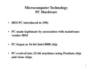
Topic 1 - Physical Form Factors • Personal Computer – Extended Technology (PC-XT) • Introduced by IBM, 8088 microprocessor was used. • It has socket for the processor and chips
Topic 1 - Physical Form Factors • AT and Baby AT • To overcome the problem created by AT Form factor, the Baby AT form factor was introduced. • Baby AT is designed to hold the peripheral devices like keyboard, video and mouse. • It could not accommodate the combination of processor, heat sink and fan. Cooling
Topic 1 - Physical Form Factors • ATX and Micro ATX form factor • Here expansion slots were placed on separate riser cards. • It provides software controlled shut down and power up. • Micro ATX form factor • More space for I/O connectors was provided at the rear end.
Topic 1 - Physical Form Factors • LPX and Mini-LPX • It has sound and video to be integrated on to the motherboard. • It is not suitable for upgrading and offers poor cooling. • NLX • Small in size • Suited for low profile desktop cases
Topic 2 - Motherboard Components • The major components of the motherboard • Processor socket or slot • Chipset • Super I/O chip • BIOS • SIMM/DIMM sockets • Bus slots
Topic 2 - Motherboard Components • Chipset and Functions • Different chips integrated to a single chip called the chipset. • North bridge and South bridge was introduced to the motherboard with PCI slots. • The south bridge controls the slower I/O components like the Serial ports, USB ports and the IDE.
Topic 2 - Motherboard Components • The new technology, Intel Hub Architecture (IHA) uses two chips called hub controllers. • The hub controllers are • Graphics and Memory Controller Hub (GMCH) • I/O Controller Hub (ICH) • The chipset determine • The voltage provided to the processor • Number of processors that can be supported • The speed of the processor • The different memory modules that are supported • Bus speed • The different expansion bus that are supported • Power Management
Topic 3 - System Chipset and Controllers • The system chipset and controllers are the intelligence of the motherboard. • Chipset has a effect on the quality, feature set and speed of the computer. • Controllers found on motherboards • The system chip • The keyboard controller • The super I/O chip • Additional built-in controllers
Topic 3 - System Chipset and Controllers • Qualities and Functions of Chipset • Chipset Processor Support • Support for Processor Class and Optimization - Supports one generation of processors • Support for Processor Speed - Fast processors need chipset control circuitry that has the capacity to manage them. • Support for Multiple Processor - Chipset support the capability for building motherboards with two or four processors on them.
Topic 3 - System Chipset and Controllers • Chipset Cache Support - The cache stores recent memory accesses by the processor • Size of Secondary Cache - Chipsets support cache of 256KB or 512 KB. • Type of Secondary Cache - three major kinds of cache, Asynchronous, Synchronous burst, Pipeline burst. • Write Policy of Secondary Cache - A write-through cache and a write back cache. • Cacheability of System Memory - The amount of cacheable memory is dependent on the chipset control circuitry and the amount of tag RAM on the board.
Topic 3 - System Chipset and Controllers • Chipset Memory Support - The chipset determines several permissible features of the memory • Support for Maximum Memory-Determines the maximum quantity of RAM a system can have on the motherboard • DRAM Technology - Regulates whether motherboard can make use of FPM, EDO, BEDO, or SDRAM memory. • Support for DRAM Packaging and Size - Two main types of memory packages are, single in-line memory module (SIMM) and dual in-line memory module (DIMM). • Support for Parity and Error Correction - Error correction logic is offered as part of the memory control circuits of the chipset.
Topic 3 - System Chipset and Controllers • Chipset Peripheral and I/O Bus Control - Most recent computers use two buses, (ISA) bus and l component (PCI) bus. • Bus Types - The chipset determines what type of buses the system can support. • Bus Bridges – Bridge is used for connecting together devices on two different buses. • IDE/ATA Hard Disk Controller - All motherboards have integrated into them support for four IDE hard disks • DMA Controller and DMA Mode Support – Process of transferring information directly to and from memory with no interference of the processor.
Topic 3 - System Chipset and Controllers • Interrupt Controller • USB Support • AGP Support • Plug and Play
Topic 3 - System Chipset and Controllers • Chipset Power Management Support – Works through a number of BIOS settings that determine when to shut down different parts of the computer • Energy Star • Advanced Power Management • Display Power • Management Signalling • System Management Mode • Hard Disk Spindown
Topic 3 - System Chipset and Controllers • Super I/O Controller Chip super I/O controller handles three ports • Serial Port Control – controls the serial ports, UART • Parallel Port Control – manages and controls the parallel port • Floppy Disk Drive Control – supports the Floppy Disk Drive and floppy based tape drives
Topic 3 - System Chipset and Controllers • Processor • Two major components • Arithmetic and Logic Unit (ALU) – performs Arithmetic and Logic Operations • Control Unit (CU) – provides the control signals for performing different operations. • Cache Memory • It is high speed storage memory made of Static RAM (SRAM). • Two types of cache memory are L1 or the internal cache and L2 cache or the external cache.
Topic 3 - System Chipset and Controllers • I/O Ports • Each device connected to a computer uses I/O port address. • Functions of I/O address • Sending commands to the peripheral device • Receiving the status of the device whether it is idle or busy • Send and receive data • Configure the device for interrupts • Bus Speed • The speed of the bus refers to the amount of the data that can be transferred across the bus.
Topic 3 - System Chipset and Controllers • Some of the bus types are, • Front side Bus - The bus speed in general refers to the speed of the Front Side Bus (FSB). • AGP Bus – It connects the video card to the memory and the CPU. • Back side Bus – It connects the processor to the L2 Cache
Topic 3 - System Chipset and Controllers • Memory bus – It connects the north bridge to the memory. • IDE or ATA bus – It connects the south bridge to the disk drives. • PCI Bus – It connects the PCI slots to the south bridge.
Topic 3 - System Chipset and Controllers • Jumpers • It is a small connector which can be placed between two pins to make electrical connections. • DIP switch • The dual inline package switch is a small block provided with a lever.
Topic 4 - CMOS Settings • CMOS BIOS ROM • Stores the basic system configuration. The four major components of BIOS are • POST • Bootstrap Loader • CMOS Setup • BIOS ROM
Topic 4 - CMOS Settings • CMOS Battery • Battery is used to power up the Real time Clock Chip. • This chip maintains the system date and time. • System Configuration • The BIOS should find an operating system on a hard disk or floppy disk drive to start the computer. • Starting the Setup Program • The settings made in the BIOS setup program are stored in the nonvolatile RAM of the CMOS chip.
Topic 4 - CMOS Settings • Step-by-Step CMOS/BIOS Configuration • From the CMOS setup menu, select the menu point to examine or change setting and choose Standard CMOS setup to begin.
Topic 4 - CMOS Settings • From the standard CMOS configuration screen you can set Date, Time, Hard drives connected to the IDE interface, Floppy disk drive types for drives
Topic 4 - CMOS Settings • Advanced CMOS Configuration • Here, you can perform the Number Lock setting, keyboard repeats speed, type of video, settings for cache memory, and other special features.
Topic 4 - CMOS Settings • Recommended Advanced CMOS Settings • Depending on the BIOS version, you have to press the ESC key, to return to the main menu
Topic 4 - CMOS Settings • Power Management Configuration • After a user defined period of inactivity of devices like the monitor, the hard drive, or the CPU will go into different low power modes. • Standby mode • Suspend mode
Topic 4 - CMOS Settings • Built-In Ports/Peripherals Setup • It can enable or disable ports which built in new systems.
Topic 4 - CMOS Settings • Security/Passwords • Two types of passwords are • One must be entered to allow any use of the system • Another one must be entered to allow access to the BIOS/ CMOS setup • Saving and Recording BIOS/CMOS Settings • BIOS allows you to save the changes and it will reject the changes that happen accidentally. • Record the critical BIOS settings
Topic 4 - CMOS Settings • BIOS Upgrades • Change the physical chip or to change its contents with software • Flash BIOS Upgrade • Install the BIOS upgrade loader and BIOS image to a floppy disk • Incorrect CMOS Configuration • Restart by using the BIOS Setup auto-configure options, double-check drive configurations, save changes, and restart.
Topic 4 - CMOS Settings • Incorrect Flash BIOS or Failed Update • If the update can't be installed, the motherboard might have jumpers that write-protects the flash BIOS. • Clearing the BIOS Password • It can be cleared by using a CMOS jumper that is present in the motherboard.
Topic 5 - Power On Self Test (POST) Error codes • Some main functions of BIOS during POST • Helps to start the Operating System. • Check for the integrity of the BIOS code • Some error beeps • No beep - Power supply or system board problem • 1 long, 1 short beep - System board problem • Long beeps - 3270 keyboard card • Some error codes • 100 to 199 - System board • 200 to 299 - Memory • 300 to 399 - Keyboard
Topic 6 - System Resources • System resources are components that are required to communicate between the hardware components in a PC. • Interrupt Request Channels (IRQ) • Hardware devices use IRQ signal to the processor • There are 16 IRQ channels .
Topic 6 - System Resources • The snapshot shows the different IRQ channels associated with different devices.
Topic 6 - System Resources • Direct Memory Access (DMA) channels • Here the data is transferred between the peripheral device and the memory without the intervention of the CPU. • Devices connected to serial and parallel port do not use DMA channels • I/O Port Address • It is an interface present in a PC to connect devices • The port address ranges from 0000h to FFFFh
Topic 6 - System Resources • The snapshot displays the I/O address range used by different devices
Topic 6 - System Resources • Checking for Resource Availability • For Windows 3.x or MS-DOS, the resource settings can be verified by using the MSD command present in the DOS directory. • For Windows 2000 or Windows XP, follow the step given below to identify the resources used by the different devices Click Start ProgramsAccessories System Tools-> System Information
Lesson 2 - Standard Expansion Buses • Introduction • The expansion slots are used to enhance the features of the PC. • The expansion slots can hold expansion cards like the sound card, VGA card, AGP card, Network card etc • There are different types of expansion slots. Industrial Standard Architecture (ISA) bus • Micro Channel Architecture (MCA) Bus • Extended ISA (EISA) Bus • Video Electronics Standard Association (VESA) Bus • Peripheral Component Interconnect (PCI)Bus • Peripheral Component Interconnect – X • Accelerated Graphics Port • Audio Modem Raiser and Communication Network Raiser
Lesson 2 - Standard Expansion Buses • Topics Covered in this Lesson • PC Bus • Industrial Standard Architecture (ISA) Bus • Micro Channel Architecture (MCA) Bus • Extended ISA (EISA) Bus • Video Electronics Standard Association (VESA) Bus • Peripheral Component Interconnect (PCI) Bus • Accelerated Graphics Port • Audio Modem Raiser and Communication Network Raiser
Topic 1 – PC Bus • PC bus is an 8 bit expansion slot to connect 8 bit expansion cards.
Topic 2 - Industrial Standard Architecture (ISA) Bus • ISA bus is a 16 bit slot present in 80286, 80386, 80486 and Pentium systems. • The ISA card is configured through jumpers or switches
Topic 3 - Micro Channel Architecture (MCA) Bus • Bus Mastering - The components that can take control over the bus are called bus masters. • Features of MCA • It is a 16 or 32 bit bus created by IBM • Supports bus mastering • Operates at 10-12 MHZ • Can be configured through software • Has Lower Noise Level
Topic 4 - Enhanced ISA • It is a 32 bit bus. • Capable of using multiple bus mastering devices. • Compatible 8 bit PC bus, 16 bit ISA bus. • Software setup capability for boards
Topic 5 - Video Electronics Standard Architecture (VESA) bus • It is a 32 bus. • It is used to connect video cards, I/O cards and multimedia expansion cards • Disadvantages of the VESA • 80486 dependence • Limited number of slots • No bus mastering • Boards are configured through jumpers
Topic 6 - Peripheral Component Interconnect (PCI) bus • PCI • Operates at a speed of 33 MHz or 66 MHz • It is a 64 bit bus • Communicates with processor using a bridge circuit. • PCI-X • Operates at 133 MHz bus speed • Offers 64 bit Band width • Supports 1 GB/Sec data transfer rate • Supports efficient bus operation • Provides backward Compatibility
Topic 7 - AGP Bus • It is designed for connecting video cards. • PCI bus with 2.1 version at 66MHZ is the basis for AGP slot. • It supports a new technique called texture cache.