Download
1 / 27
280 likes | 302 Views
Understand band theory of solids, interaction of atoms, semiconductor properties, diode circuits, and bipolar junction transistors. Learn the operation, biasing, and characteristics of electronic devices.

E N D
Band theory of solids • situation when two hydrogen atoms are brought together. • interaction between the electrostatic fields of the atoms split each energy level into two, • gives one level slightly higher than before and another one slightly lower
BAND GAP 1 ATOM 2 ATOMS MANY ATOMS Band theory of solids
CB CB CB EG EG VB VB VB Insulators, Semiconductors and Metals
The Bond Theory • 1. Ionic bonds: electrostatic attraction between the ions. Atoms donate/accept electrons to become +vely or -vely charged ions. • 2. Covalent Bonds: Atoms joined by sharing valence electrons. • 3. Metallic bonds: exhibited by electrons with single valence electrons, e.g. Cu, Na, Ag, Au. substances find minimum energy configuration when they pool their valence electrons. The electrons are no longer tied to specific sites (atoms) but are unlocalised and are free to travel throughout the metal forming an electron cloud.
Intrinsic and Extrinsic semiconductors intrinsic Extrinsic (with P) Extrinsic with Al (Gp 4 elements)
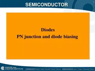
III DIODE CIRCUITS AND CHARACTERISTICS
DIODE CIRCUITS AND CHARACTERISTICS • P-n junction: • 1. depletion layer established on both sides of the junction. • 2. barrier (junction) potential is developed across the junction. • 3. Formation of junction and diffusion capacitances.
p n + + + + + + + + + + + + + + - - - - - - - - - - - - - - - - - - - - - - - - Free (mobile charges) + + + + + + + + + + + + - - - - - - - - - - - - + - - + Depletion layer with fixed ions P-n junction (a) depletion region
p n Depletion layer VB 0 + + + + + + + + + + + + + + + + + + - - - + + + - - - - - - - - - - - - - - - - - - (b) Junction or barrier potential
+ + + + + + + + + + - - - - - - - - - - Forward biased p-n junction. O ( Ih ) e ( Ie) I VA 0 VB - VA EC q(VB – VA) EF qVA EV
Si Ge I V Vγ Forward I-V characteristics.
e O VA + VB q(VB + VA) qVA + + + + + + - - + + - - - - - - Reverse Biased p-n Junction.
Reverse I-V characteristics Reverse voltage Forward voltage I (μA)
Diode Law • For ideal diode: • iD = 0, vD 0, • vD = 0, iD > 0, • With eqn
1 2 3 Diode Law • 1. • 2 VA = 0, I = 0 • 3 4
v vi RL vi i Rectifier circuits
E C E C B B N P N P P N N P P N P N Bipolar j. transistor
Biasing PN junctions. E C • B-E junction forward biased by VEE • -ve terminal of VEE connected to n-side • flow of id across due to flow of majority carriers (electrons) from the N-type emitter • become minority carriers in the base B VEE Forward biased B-E (input) junction
C E B VCC Reverse biased C-B (output) junction • C-B reverse biased by VCC • +ve of VCC connected to N-type collector • depletion region at the junction widens • current flowing from B-E due to minority electrons crossing the junction from p-type base. • constitute flow of reverse current in the junction.
Simultaneous biasing e • B is ground (0V) • E is -ve wrt B & C is +ve wrt B • e- flow constitutes the dominant type (in npn) • IE = IC + IB IC IB IE VEE VCC npn
IE IB IC VEE VCC • IC sum of the injected & thermally generated minority carriers. • if VEE is left open, & C-B has normal reverse bias • Then ICBO will flow • Hence total I is • IC = IC(Inj) + ICBO or (IC = ICBO - IE) • Where IC(Inj) is IC due to carriers injected into the base. pnp
portion of IC that survives after passing through the B to become IC
IC IE E C IC IE - + E C - + VBC = Output voltage VEB = Input Voltage VCB = Output voltage VBE = Input Voltage IB B IB - + B + - CB connection NPN PNP SCI 2010/2011 simiyuj@uonbi.ac.ke
Increasing output bias VCB = 25V IE (mA) VCB = 10V VCB = 0 VBE (V) CB Input Characteristics • F-B diode (input is across the forward-biased B-E junction) • greater the value of VCB, the more readily minority carriers in the base are swept through the B-E junction. (VBE = Φ(VCB, IE))
CB Output characteristics saturation • Active: • IE = 0, IC = ICO • IC rises with VCB & IC is slightly less than IE since IC =- IE and ≈ 1 • Saturation • VCB is +ve and the junction is forward biased • I.e C-B & E-B are forward biased Active region IE ICO Cut off (IC = Φ(VCB, IE))