Download
1 / 19
200 likes | 343 Views
Cryomodule Helium Vessel Pressure -- a Few Additional Comments. Tom Peterson 18 November 2007. Update of Oct 2007 Comments. October, 2007, slides summarizing helium vessel pressure issues are appended here

E N D
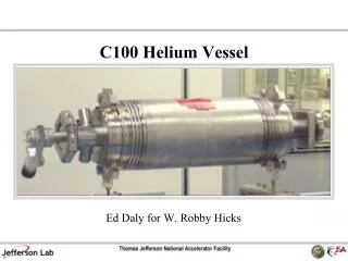
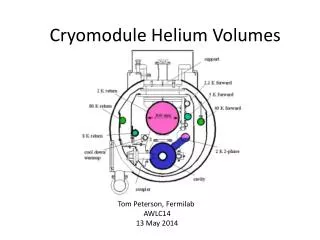
Cryomodule Helium Vessel Pressure -- a Few Additional Comments Tom Peterson 18 November 2007
Update of Oct 2007 Comments • October, 2007, slides summarizing helium vessel pressure issues are appended here • We should review helium vessel maximum pressures in light of DESY “crash test” and pressure tests • We should review vacuum vessel venting in light of LHC magnet vacuum space overpressure incident He pressure excursions
Crash and pressure test comments • 2 bar warm and 4 bar cold maximum differential pressures (MAWP) were an initial compromise choice • 2 bar warm for cryogenic operation • 4 bar cold to accommodate worst-case loss of vacuum pressure rise • DESY crash test slow pressure development at 2 K with maximum of about 2.5 bar • 4 bar MAWP looks conservatively high • Still need to evaluate maximum pressure with venting path from string of cryomodules • Pressure test indicates possibility of one pressure rating -- 4 bar warm or cold • Means pressure testing at around 5 bar warm He pressure excursions
Vacuum vessel venting • Can LHC-type accident occur in SRF string? • LHC (my unofficial account of the events) -- electrical arc, rupture of 2 K helium bellows and release of helium into insulating vacuum space at LHC • LHC magnets quenched into insulating vacuum space • Pressure starts at about 1.2 bar nominal • Flow driven by higher pressure from magnet string quench • In contrast, 2 K RF system starts at 30 mbar • 2 K RF system does not have the stored energy of a magnet system • LHC high pressure (~16 bar) thermal shield line also subsequently ruptured into vacuum space • Several sources of pressure due to rupture of several lines • Magnet motion due to pressure in vacuum space He pressure excursions
ILC vacuum vessel venting • Low pressure and low stored energy in 2 K part of SRF system • However, ILC concept includes high pressure shields • 18 - 20 bar is current plan, but pressures need to be evaluated with cryogenic plant cycle • In any case, shield pipe up to 80 mm ID, so potentially very large flow into vacuum space • Cryomodule strings will require large and frequent vacuum relief ports • Need to evaluate path to relief port (through thermal shields, not blocked by MLI, etc.) • XFEL is also re-evaluating vacuum space venting requirement He pressure excursions
Reference slides From October, 2007
Cryogenic plant arrangement He pressure excursions
Causes of pressure excursions • Worst case location is probably always the cavity helium vessels in the string 2.4 km from the cryogenic plant • Purification and cool-down flow • Warm-up flow • Compressor failure (e.g., power outage) • Control and/or valve failures • Loss of insulating vacuum while cold • Loss of cavity vacuum while cold He pressure excursions
A cryogenic “string” He pressure excursions
Type 4 cryomodule pipe sizes He pressure excursions
Pipe size summary as of July 07 He pressure excursions
Purification and cool-down • XFEL paper states that the 2.2 K supply line limits flow, confirmed above • Numerical simulations for the cooldown of the XFEL and TTF superconducting linear accelerators by K. Jensch, R. Lange, B. Petersen • Appears to be less than 0.1 bar delta P in line B for all possible warm flow conditions as limited by line A. He pressure excursions
Compressor shutdown • Suction pressure rises to the suction relief valve settings • Pressure sits at the suction relief pressure while helium vents • Unlike higher pressure reliefs, helium must vent outside of system • Large loss of helium inventory • Low pressure volume of 210,000 liters per cryogenic unit • However, each 0.1 bar helium = only about 26 liquid liters equiv • Need relief set pressure safely above anticipated operating pressures to avoid accidental, unnecessary, loss of helium He pressure excursions
Peak warm pressure • Compressor suction set pressure • 1.2 bar • Control margin • +/- 0.2 bar • Relief set pressure margin • 0.3 bar (a judgment here, would like 0.5 bar) • Suction relief set pressure • 1.7 bar • Pressure drop from far string • 0.1 bar • Peak warm pressure • 1.8 bar (note that 0.5 bar set P margin ==> 2.0 bar) He pressure excursions
Cold peak pressures - 1 • Loss of vacuum to air • “Safety Aspects for the LHe Cryostats and LHe Containers,” by W. Lehman and G. Zahn, ICEC7, London, 1978 • “3.8 W/sq.cm. for an uninsulated tank of a bath cryostat” • “0.6 W/sq.cm. for the superinsulated tank of a bath cryostat” • “Loss of cavity vacuum experiment at CEBAF,” by M. Wiseman, et. al., 1993 CEC, Advances Vol. 39A, pg 997. • Maximum sustained heat flux of 2.0 W/sq.cm. • LEP tests and others have given comparable (2.0 to 3.8 W/sq.cm.) or lower heat fluxes • Film boiling of helium with 60 K surface is about 2.5 W/sq.cm. He pressure excursions
Cold peak pressures - 2 • Relief pressure will be suction relief set pressure (for example, 1.7 bar) • Heat flux of 10’s of KW to liquid helium • Mass flows of many kg/sec • Pressure drops to vent may result in peak pressures of 3 - 4 bar locally • TTF, TESLA, and XFEL analyses have been done • Fermilab has done analyses of single cavity systems He pressure excursions
Cold peak pressures in TTF/ILC • Analyses of TTF and TESLA back in the early 1990’s indicated that worst-case loss of vacuum might lead to pressures near 4 bar cold • Also have recent XFEL analysis (need to find, but comparable results, no more than 4 bar) • Input parameters • Heat flux as limited by • Rate of air inleak • Suface heat transfer • Total surface area involved • Can be limited by vacuum breaks, fast valves • Initial conditions • Note that 4.5 K just after filling is the worst case! He pressure excursions
Ongoing work • Analyses already done for single-cavity system • Include FEA of helium vessels • Include venting and pressure drop calculations • Working on full cryomodule pressure analysis now • Needed for ILCTA-NML • Cryogenic end boxes on order • Engineers are working on helium vessel design for pressure containment with low stress (Fermilab and INFN) • End group stresses and design • Bellows stresses design • Tuner loads, stresses, and design • RF cavity stresses • Venting and pressure limits are a cryogenics WP He pressure excursions
Pressure tests • DESY will do cold vacuum loss studies of a cryomodule at CMTF • Labs could do warm tests of pressure effect on cavity tune • What pressure warm results in some permanent detuning, some yielding • Do not yet see from analyses what is yielding at 2 bar -- should validate analytical models • Labs could do cold tests • Sequentially pressurize at 5 K, reduce pressure and test at 2 K, (perhaps 4.2 K?), etc. He pressure excursions