Download
1 / 24
260 likes | 380 Views
Cavity, helium vessel and tuner assembly. N. Valverde , G. Arnau, S. Atieh, I. Aviles, O. Capatina, M. Esposito, F. Pillon, T. Renaglia, T. Tardy. CERN, 4 Nov. 2011. INTRODUCTION- CAVITY SPL. A string of 4 equipped β =1 bulk niobium cavities to be tested into a short cryo -module.

E N D
Cavity, helium vessel and tuner assembly N. Valverde , G. Arnau, S. Atieh, I. Aviles, O. Capatina, M. Esposito, F. Pillon, T. Renaglia, T. Tardy CERN, 4 Nov. 2011
INTRODUCTION- CAVITY SPL A string of 4 equipped β=1 bulk niobium cavities to be tested into a short cryo-module 1490.5 mm
OVERVIEW • CAVITY • HELIUM TANK • TUNER • POWER COUPLER • INTERCAVITY SUPPOR SYSTEM • HOM COUPLER • INTERFACES INTER-CAVITY • CONCLUSIONS
INTRODUCTION- CAVITY SPL Helium tube Helium Tank Bellows Tuner Bulk Niobium 5Cells cavity Magnetic shielding Hom Coupler Interface tank Power Coupler
CAVITY Dimensions at warm temperature 5-cellcavity Material: Bulk Niobium Flanges: SS Frequency: 704.4 MHz Quality factor: 1010 Nominal gradient Eacc= 25 MV/m 1397.3 mm 79.7 381.7 106.6 Min Thck= 3mm 100 79.7 4 cavities to be manufactured : 3 at the industry + 1 at CERN (Tbc) 45 Standard delivery: 11 M
CAVITY Half-cells fabricated by spinning and welded by EB welding. Cavity made of Niobium and SS flanges Nb tubes are joined to the SS CF flanges by Brazing with pure Cu filler metal. The joint of the SS bellow support to the Nb cavity also by brazing. Min Thck= 3mm
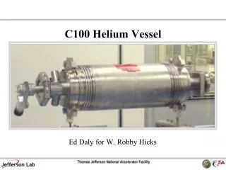
HELIUM TANK • Designed by CERN (SS material) • To be manufactured by CEA • Assembly cavity-tank by CERN
HELIUM TANK 2 Functions are fulfilled: Cryogenic– Keep the helium II (2K) and allowing extraction of the heat dissipated into the cavity. Structural – To transmit the effort applied by the tuner to the cavity. Design pressure 1.5 bars => not considered as pressure vessel
HELIUM TANK Support for helium tube
HELIUM TANK Interface for alignment supports The alignment system supports are designed by the cryo-module team compatible with all adjacent equipment (magnetic shielding etc...)
HELIUM TANK Handling support Fixation for Magnetic shielding
HELIUM TANK- Interface Cryo SS CF UHV DN100, tube dia 80 mm -It has been designed to extract the heat in a nominal performance (pulsed). SS CF UHV DN 40, tube dia 27 mm. In principle not needed in a first phase. Will be closed with a flange. Needs to be defined by cryo if instrumentation (ex. heaters...) or other equipments (ex. helium supply pipe...) need to be installed before assembly of the helium tank.
TUNER • To besupplied by CEA • To beinstalled by CERN during the assembly of the cryo-module • Instrumentation / control cables
POWER COUPLER Designed and provided by CERN (BE/RF) 2 flanges SS CF UHV DN 100, tube DIA 100 CF “RF type LHC” gasket Schematic view • Requirements to fulfill: • RF Electric continuity • Support for the cavity (The cavity + tank is not designed for cantilever supporting)
POWER COUPLER • The double-walled tube of the main coupler will need to be actively cooled • The cooling circuit in/out are foreseen inside the cryostat vacuum See talk Paulo for more info double wall coupler
Intercavity support system 2 flanges SS CF CF “RF type LHC” gasket Interfaces foreseen on the helium tank for the second support of the cavity: the « intercavity supporting system » See talk Arnaud for more info inter-cavity supporting system
HOM COUPLER HOM: Not installed at the first stage. The cavity will be delivered closed with a flange at the HOM port. It has to be foreseen a cooling system at the cryo-module for the HOM installation in a later phase.
INTERFACES INTER-CAVITIES SS bellow not actively cooled. CF SS flanges + standard gasket. Instrumentation cable (temperature) to be foreseen. Position for Temperature measurement
Conclusions Niobium cavities manufacturing procedure ongoing. This review will allow us to go ahead (or modify) with the design of the helium tank for the cavities. This design has then to be provided to CEA for manufacturing.
Train de cavite assemble en Salle blanche Prévoir Piece intermediaire
Brazing Nb / SS 316 LN is a key technology Developed at CERN in the 1987. Joint design: Difference in dilatation of Nb/SS Nb tube fitted to SS flange Clearance ≤ 20 µm SS plug to expand the Nb Pure Cu filler metal Brazing temperature 1100°C, ∆time << P< 10-5 mbar