Download

1 / 21
930 likes | 4.7k Views
Strain Gage Theory. UAA School of Engineering CE 334 - Properties of Materials Lecture # 18. What are Strain Gages?. One of several devices that can be used to obtain strains directly. A small device that can be attached directly to the item for which strain data is required.

E N D
Strain Gage Theory UAA School of Engineering CE 334 - Properties of Materials Lecture # 18 Strain Gage Theory
What are Strain Gages? • One of several devices that can be used to obtain strains directly. • A small device that can be attached directly to the item for which strain data is required. • The device measures strain at the surface of an structural element. • A strain gage is a small wire grid whose electrical resistance changes as it strains. Strain Gage Theory
Basic Principle • Professor William Thomson (Lord Kelvin) was the first to discover the relationship between electrical resistance of wires and induced strains. • Strains imposed by tensile stresses cause an increase in electrical resistance. • Strains imposed by compressive stresses cause a decrease in electrical resistance. Strain Gage Theory
Uses of Strain Gages • Valuable tool for use by stress analysts. • Analyze new designs (prototypes) • Trouble shooting and correcting old designs. • Service load analysis • Theoretical investigations • Control systems. Strain Gage Theory
Wheatstone Bridge • Wheatstone bridge (an electrical circuit devised by Sir Charles Wheatstone) is most commonly used to determine the change of electric resistant. • R1 is the active gage and is placed at the location where strain is to be measured. • R2 is a dummy gage. • R4 is a precision variable resistor. • Galvanometer is calibrated to read in strain units. Strain Gage Theory
Measurement of Change in Resistance • Resistance changes are small. On the order of thousandths of an ohm. • Bridge is balance when Ig=0: I1R1 = I2R2 and I1= I4,I2=I3, I1R4 = I2R3 or I1/I2=R2/R1, I1/I2=R3/R4, R2/R1 =R3/R4 R1 = (R2/R3)R4 Strain Gage Theory
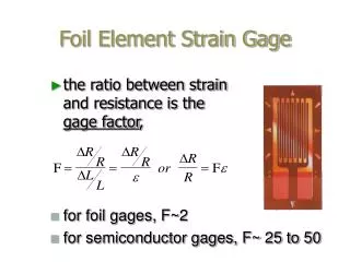
Gage Factor • Thegage factor, K, of a strain gage relates the change in resistance(R) to the change in length(L). This is constant for a given strain gage. • K = (R/R)/(L/L) = (R/R)/. • Rearrange the terms to get: = (R/R)/K • Once installed, we read the change in resistance (R) and use the above equation to determine the strain (). Strain Gage Theory
Points to be considered in selecting a resistance alloy • Gage Factor (The higher the better) • Resistance (The higher the better) • The effect of temperature • Relationship between the change in resistance and strain (should be linear) • Wire size (small so as to be weaker than adhesive) Strain Gage Theory
Temperature Compensation: Temperature Compensation • Reasons: • The resistance of the wires changes with temperature. • If the temperature coefficient of the strain gage differs from that of the specimen, there are some temperature effects in the readings. • Temperature effects are compensated for by attaching the dummy gage R2to the specimen in such a way that it is not strained. R1/R4 = R2/R3 at the balance condition. if R1 ~= R2 and R1 = R2 then (R1+R1)/R4 = (R2+R2)/R3 Strain Gage Theory
Temperature Compensation: Temperature Compensation and Doubling output on aBendingMember • Attach the two active gages onopposite sides. • The circuit not only compensates for temperature but also doubles the sensitivity. • Because with R1 in compression and R2 in tension,the resistant changes of opposite signs in effect add together. R1 R2 R4 R3 Strain Gage Theory
Temperature Compensation: Poisson Arrangement • Temperature compensation only. • Attach both gages to same side but at one perpendicular to the direction of stress. • Need to know Poisson’s Ratio to compensate for strain in the dummy gage. R1 R2 R4 R3 Strain Gage Theory
FilteringBendingForces P e • R1’ and R1 are used as the active gages on opposite sides. • The strain in R1>Raxial,in R’1<Raxial. • The circuit adds their results and divides by two. Errors are canceled out. • It gives the true axial strain irrespective of any bending. R1’ R2’ R1 R2 R4 R3 Strain Gage Theory
Placement on Shaft inTorsion • All four gages used. • Output is quadrupled. • Temperature is compensated. • Gages are measuring the principle strains. R1 R2 R4 R3 Strain Gage Theory
Multi-element Strain Gages • Multi-element strain gages have 2 or more strain gages built into them. • The orientation of the gages relative to each other is fixed. • Using Mohr’s Circle for strain, the magnitude and direction of the principle stresses can be computed. Strain Gage Theory
45E Rosette For the 45 deg rosette, the magnitudes of principle stresses can be determined from basic strain relationships: a b c Strain Gage Theory
60E Rosette • The principle stresses and strains can be determine from basic relationships. • Advantage of the Rosettes is that they make it possible to determinethe magnitude and directionof principle stresses when the direction is not obvious or changes with loading. Strain Gage Theory
Specialty Gages • There are a myriad of specialty gages that have been developed for special applications. • Gages may vary in types of materials used or in configuration to meet the demands of special situations. • High heat, moist environments, and large strains are examples of situations that require special gages. Strain Gage Theory
Advantages of Strain Gages • Ease of Installation • Relatively high accuracy • Adjustable sensitivity • Remote indication • Very short gage length • Response to dynamic strain. Strain Gage Theory
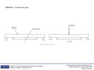
Strain Gage Testing of a Cantilever Strain Gage Theory
Strain Gage Testing of a Cantilever Objectives: 1. Assist in acquiring strain gage measurements from a cantilever beam. 2. Determine the stresses in a cantilever from the strain gage measurements. 3. Compare the results with the theoretical predictions based on ES-331, the Mechanics of Materials course. Strain Gage Theory
Strain Gage Testing Have fun! Strain Gage Theory