Download
1 / 61
620 likes | 941 Views
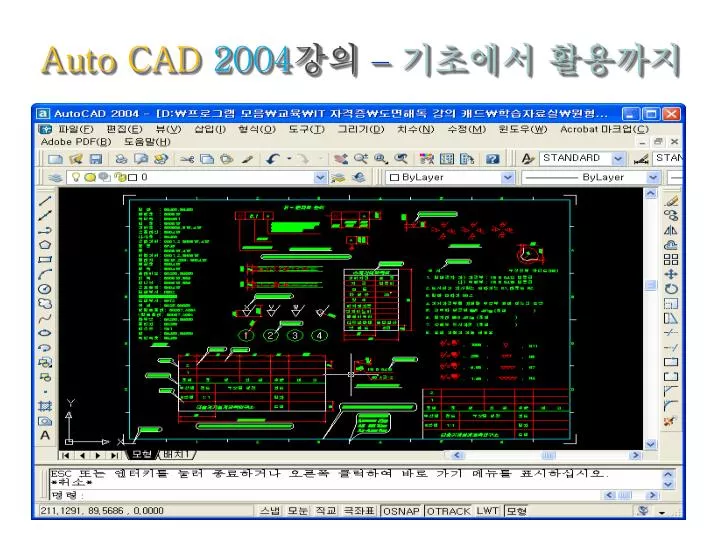
Auto CAD 2004 강의 – 기초에서 활용까지. 제 42 장 Auto CAD Solid Modeling. Solid Modeling. ♣ 앞장에서 우리는 Solid Modeling 이란 객체 내부가 채워져 있는 덩어리 형태로써 객체의 질량 , 부피 등의 정보를 얻을 수 있다고 배웠다 . 또한 Solid 객체는 내부가 채워져 있으므로 서로 더하거나 빼는 작업이 가능하다 . 그래서 3 차원 작업이 훨씬 더 쉽고 재미있으며 유용하다 .

E N D
제 42장 Auto CAD Solid Modeling
Solid Modeling ♣ 앞장에서 우리는 Solid Modeling이란 객체 내부가 채워져 있는 덩어리 형태로써 객체의 질량, 부피 등의 정보를 얻을 수 있다고 배웠다. 또한 Solid 객체는 내부가 채워져 있으므로 서로 더하거나 빼는 작업이 가능하다. 그래서 3차원 작업이 훨씬 더 쉽고 재미있으며 유용하다. 단, 3차원 형상을 Surface Modeling에 비해 쉽게 제작할 수 있지만, 많은 용량과 작업속도가 느린 단점을 가지고 있다. Solid Modeling 에 관련된 명령도 기본 툴바에는 나타나지 않으므로 아무 아이콘이나 마우스를 두고 오른쪽 버튼을 눌러 Solids 툴바를 꺼내도록 하자.
Solid Modeling [Box] ① 기능 : 3차원 솔리드 상자를 만들기 위한 명령이다. ② 명령 Command: Command: _box Specify corner of box or [CEnter] <0,0,0>:Box의 시작점 P1 지정 Specify corner or [Cube/Length]: @100,75: Box의 끝점 P2 지정 Specify height: 50: 높이 입력 ③ 옵션 -. Center : 박스의 중심 Command: Command: _box Specify corner of box or [CEnter] <0,0,0>: c Specify center of box <0,0,0>: 박스의 중심 P1 지정 Specify corner or [Cube/Length]: @50,30 : 박스 크기 지정 Specify height: 50 : 높이 입력
Solid Modeling [Box] ③ 옵션 -. Length : 박스의 길이와 넒이, 높이를 지정하여 생성하는 옵션이다. Command: Command: _box Specify corner of box or [CEnter] <0,0,0>: 상자 시작점 P1 지정 Specify corner or [Cube/Length]: l : 옵션 입력 Specify length: 100 : 길이 입력 Specify width: 75 : 넓이 입력 Specify height: 50 : 높이 지정 -. Cube : 정육면체를 생성하는 옵션이다. Command: Command: _box Specify corner of box or [CEnter] <0,0,0>: 상자 시작점 P1 지정 Specify corner or [Cube/Length]: c : 옵션 입력 Specify length: 60 : 길이 입력
Solid Modeling [Sphere] ① 기능 : 솔리드 구를 만들기 위한 명령이다. ② 명령 Command: Command: _sphere Current wire frame density: ISOLINES=4 Specify center of sphere <0,0,0>: 구의 중심 P1 입력 Specify radius of sphere or [Diameter]: 100 : 구의 반지름 입력 ③ 참고 기본적으로 Auto cad는 네 개의 등거리 선으로 솔리드를 그리게 되는데, 이 선들은 솔리드의 곡면을 정의한다. 등거리 선의 시스템 변수의 값 ( ISOLINES ) 을 증가하면 솔리드는 훨씬 좋아 보일 것이다. [Hide] 처리 전 [Hide] 처리 후 Command: ISOLINES Enter new value for ISOLINES <4>: 8 Command: Regen Regenerating layout. ISOLINES=4 ISOLINES=8
Solid Modeling [Cylinder] ① 기능 : 솔리드 원통을 만들기 위한 명령이다. ② 명령 Command: Command: _cylinder Current wire frame density: ISOLINES=4 Specify center point for base of cylinder or [Elliptical] <0,0,0>: 중심점 P1 지정 Specify radius for base of cylinder or [Diameter]: 50 : 원통의 반지름 입력 Specify height of cylinder or [Center of other end]: 100 : 원통의 높이 입력 [Hide] 처리 전 [Hide] 처리 후
Solid Modeling [Cylinder] ③ 옵션 -. Elliptical : 타원형의 원통을 만들기 위한 옵션이다. Command: Command: _cylinder Specify center point for base of cylinder or [Elliptical] <0,0,0>: e : 옵션 입력 Specify axis endpoint of ellipse for base of cylinder or [Center]: 시작점 P1 입력 Specify second axis endpoint of ellipse for base of cylinder: @100,0 : P2 입력 Specify length of other axis for base of cylinder: @0,25 : P3 입력 Specify height of cylinder or [Center of other end]: 100 : 원통의 높이 입력 [Hide] 처리 전 [Hide] 처리 후 -. Center of other end : 원기둥의 방향과 높이를 한번에 지정하는 옵션이다.
Solid Modeling [Cone] ① 기능 : 밑면이 원이나 타원으로 이루어진 솔리드 뿔을 생성하기 위한 명령이다. ② 명령 Command: Command: _cone Current wire frame density: ISOLINES=4 Specify center point for base of cone or [Elliptical] <0,0,0>: 중심점 P1 지정 Specify radius for base of cone or [Diameter]: 50 : 반지름 입력 Specify height of cone or [Apex]: 100 : 높이 입력 [Hide] 처리 전 [Hide] 처리 후
Solid Modeling [Cone] ③ 옵션 -. Elliptical : 타원형의 원뿔을 생성하기 위한 옵션이다. Command: Command: _cone Current wire frame density: ISOLINES=4 Specify center point for base of cone or [Elliptical] <0,0,0>: e : 옵션 입력 Specify axis endpoint of ellipse for base of cone or [Center]: 시작점 P1 입력 Specify second axis endpoint of ellipse for base of cone: @100,0 : P2 입력 Specify length of other axis for base of cone: @0,25 : P3 입력 Specify height of cone or [Apex]: 100 : 높이 입력 [Hide] 처리 전 [Hide] 처리 후 -. Apex : 원뿔의 방향과 높이를 한번에 지정하기 위한 옵션이다.
Solid Modeling [Wedge] ① 기능 : 솔리드 쐐기를 만드는 명령이다. ② 명령 Command: Specify first corner of wedge or [CEnter] <0,0,0>: 시작점 P1 지정 Specify corner or [Cube/Length]: @50,50 : 끝점 P2 입력 Specify height: 100 : 높이 입력 ③ 옵션 -. Center : 쐐기 경사면의 중앙점을 지정하여 생성하는 옵션이다. Command: Command: _wedge Specify first corner of wedge or [CEnter] <0,0,0>: c: 옵션 입력 Specify center of wedge <0,0,0>: 중심점 P1 지정 Specify opposite corner or [Cube/Length]: @30,30: 밑면의 크기 입력 Specify height: 70: 높이 입력
Solid Modeling [Wedge] ③ 옵션 -. Cube : 길이, 넓이,높이가 같은 쐐기를 생성한다. Command: Command: _wedge Specify first corner of wedge or [CEnter] <0,0,0>:시작점 P1 지정 Specify corner or [Cube/Length]: c: 옵션 입력 Specify length: 50: 길이 입력 -. Length : 길이,넓이,높이를 따로 지정하여 쐐기를 생성한다. Command: Command: _wedge Specify first corner of wedge or [CEnter] <0,0,0>:시작점 P1 지정 Specify corner or [Cube/Length]: l : 옵션 입력 Specify length: 70 : 길이 입력 Specify width: 40 : 넓이 입력 Specify height: 60 : 높이 입력
Solid Modeling [Tours] ① 기능 : 솔리드 튜브를 만들기 위한 명령이다. ② 명령 Command: Command: TORUS Current wire frame density: ISOLINES=4 Specify center of torus <0,0,0>: 중심점 P1 지정 Specify radius of torus or [Diameter]: 50 : 토러스 반지름 P2 입력 Specify radius of tube or [Diameter]: 10 : 튜브 반지름 P3 입력 [Hide] 처리 전 [Hide] 처리 후
Solid Modeling ♣ Solid Modeling이란 ? 객체 내부가 채워져 있는 덩어리 형태로써 객체의 질량, 부피 등의 정보를 얻을 수 있다. ♣ [Box] : 3차원 솔리드 상자를 만들기 위한 명령이다. ♣ [Sphere] : 솔리드 구를 만들기 위한 명령이다. ♣ [Cylinder] : 솔리드 원통을 만들기 위한 명령이다. ♣ [Cone] : 밑면이 원이나 타원으로 이루어진 솔리드 뿔을 생성하기 위한 명령이다. ♣ [Wedge] : 솔리드 쐐기를 만드는 명령이다. ♣[Tours] : 솔리드 튜브를 만들기 위한 명령이다.
제 43장 Auto CAD Solid Modeling 응용
Solid Modeling 응용 ♣ 앞장에서 기본 솔리드 객체를 생성하는 방법을 배웠다. 이번 장에서는 다양한 솔리드 객체를 생성하는 방법에 대해서 살펴보도록 하자. [Extrude] ① 기능 : 닫힌 Pline 형태의 객체(단면)를 Z 방향으로 돌출시켜 솔리드 객체를 만들거나 Path를 따라 돌출 시켜 객체를 만든다. 반드시 Extrude 시킬 단면은 하나의 Pline 이여야 하며, 닫힌(Close) 형태여야 한다. Surface Model을 돌출시키기 위한 [Chprop] 명령의 [Thickness] 옵션과 유사하다. ② Extrude 가능한 객체의 종류 -. Closed Polyline -. Closed Spline -. Polygon -. Donut -. Rectangle -. Region -. Circle -. Surface -. Ellipse
Solid Modeling 응용 ③ 명령 Command: Command: EXTRUDE Current wire frame density: ISOLINES=4 Select objects: 객체 P1 선택 Select objects: : 선택 종료 Specify height of extrusion or [Path]: 50 : 높이 입력 Specify angle of taper for extrusion <0>: : 돌출 각도 입력 돌출 각도(Taper Angel)=0 돌출 각도(Taper Angel)=5 돌출 각도(Taper Angel)=10
Solid Modeling 응용 [Extrude] ④ 옵션 -. Path : Path 커브를 따라 객체를 돌출시켜 솔리드를 생성한다. 이형의 솔리드 객체를 생성시키는데 매우 유용한 옵션이다. Command: Command: EXTRUDE Current wire frame density: ISOLINES=4 Select objects: 객체 P1 선택 Select objects: : 선택 종료 Specify height of extrusion or [Path]: p: 옵션 입력 Select extrusion path: Path P2 선택
Solid Modeling 응용 [Revolve] ① 기능 : 닫힌 Pline 형태의 객체를 축을 기준으로 회전시켜 솔리드 객체를 생성한다. Surface Modeling의 [Revsurf]와 유사하다. 특정한 반지름을 갖는 컵,그릇,접시 등 회전체의 생성에 유리하다. Revolve 시킬 개체로는 면적을 가질 수 있는 폐합된 하나의 곡선, 직선만이 가능하다. 폐합되지 않은 객체를 선택하면 에러가 발생되며 명령이 종료된다. ② 명령 Command: Command: _revolve Current wire frame density: ISOLINES=4 Select objects: 객체 P1 선택 Select objects: : 선택 종료 Specify start point for axis of revolution or define axis by [Object/X (axis)/Y (axis)]: 회전축의 첫번째 점 P2 지정 Specify endpoint of axis: 회전축의 두번재 점 P3 지정 Specify angle of revolution <360>: : 회전 각도 지정
Solid Modeling 응용 [Revolve] ③ 옵션 -. Object : 회전축으로 지정할 객체를 선택하기 위한 옵션 Command: Command: _revolve Current wire frame density: ISOLINES=4 Select objects: 객체 P1 선택 Select objects: : 선택 종료 Specify start point for axis of revolution or define axis by [Object/X (axis)/Y (axis)]: o: 옵션 입력 Select an object:축으로 지정할 객체 P2 선택 Specify angle of revolution <360>: : 회전 각도 지정
Solid Modeling 응용 [Revolve] ③ 옵션 -. X / Y : 현재 UCS의 X,Y 방향을 회전축으로 설정하기 위한 옵션 Command: Command: _revolve Current wire frame density: ISOLINES=4 Select objects: 객체 P1 선택 Select objects: : 선택 종료 Specify start point for axis of revolution or define axis by [Object/X (axis)/Y (axis)]: y: 옵션 입력 Specify angle of revolution <360>: : 회전 각도 지정 X (axis) Y (axis)
Solid Modeling 응용 [Slice] ① 기능 : 솔리드 객체를 자르기 위한 명령이다. ② 명령 Command: Command: _slice Select objects: 객체 선택 Select objects: : 선택 종료 Specify first point on slicing plane by [Object/Zaxis/View/XY/YZ/ZX/3points] <3points>: 첫번째 점 P1 선택 Specify second point on plane: 두번째 점 P2 선택 Specify third point on plane: 세번째 점 P3 선택 Specify a point on desired side of the plane or [keep Both sides] : B를 입력하여 양쪽 모두를 남기거나, 남기고 싶은 쪽 P4 선택
Solid Modeling 응용 [Slice] ③ 옵션 -. Object : Pline 형태의 객체(원,호,Pline,타원,Polygon 등)를 자를 단면으로 이용하여 객체가 이루는 면을 자름. (객체의 각도나 방향, 위치에 따라 잘리는 면이 결정) Command: Command: _slice Select objects: 객체 선택 Select objects: : 선택 종료 Specify first point on slicing plane by [Object/Zaxis/View/XY/YZ/ZX/3points] <3points>: o Select a circle, ellipse, arc, 2D-spline, or 2D-polyline: 단면 P1 선택 Specify a point on desired side of the plane or [keep Both sides] : B를 입력하여 양쪽 모두를 남기거나, 남기고 싶은 쪽 P2 선택
Solid Modeling 응용 [Slice] ③ 옵션 -. Zaxis : 지정한 Z축 방향에 대한 XY 평면을 자른다. Specify point an plane: XY 평면에 점을 입력한다. Specify point Z-axis (Normal) of the plane : Z축 선상에 한 점을 입력한다. -. View : 2차원의 자르는 평면을 현재 뷰포트의 보는 평면과 정렬한다. 현재 바라보는 방향의 면을 자른다. Specify point on view plane <0,0,0> : 점을 입력한다. -. XY / YZ / ZX : 2차원의 평면을 현재 UCS의 평면과 정렬한다. 점을 지정하여 평면의 위치를 다음과 같이 정하여야 한다. Point on XY plane <0,0,0> : 점을 입력한다.
Solid Modeling 응용 [Section] ① 기능 : 솔리드 객체의 단면을 생성하기 위한 명령이다. [Slice]와 명령의 진행은 유사하나. 솔리드 객체를 절단하지 않고, 절단되는 면에 Region 객체를 생성한다. ② 명령 Command: Command: _section Select objects: 객체 선택 Select objects: : 선택 종료 Specify first point on Section plane by [Object/Zaxis/View/XY/YZ/ZX/3points] <3points>: 첫번째 점 P1 선택 Specify second point on plane:두번째 점 P2 선택 Specify third point on plane:세번째 점 P3 선택
Solid Modeling 응용 [Slice] ③ 옵션 -. Object : Pline 형태의 객체(원,호,Pline,타원,Polygon 등)를 이용하여 객체가 이루는 면의 단면을 생성. Command: Command: _section Select objects: 객체 P1 선택 Select objects: : 선택 종료 Specify first point on Section plane by [Object/Zaxis/View/XY/YZ/ZX/3points] <3points>: o Select a circle, ellipse, arc, 2D-spline, or 2D-polyline: 단면 P2 선택 -. Zaxis : 지정한 Z축 방향에 대한 XY 평면의 단면을 생성한다. -. View : 현재 바라보는 방향의 면의 단면을 생성한다. -. XY/YZ/ZX : 지정한 UCS 면의 단면을 생성한다.
Solid Modeling 응용 [Interfere] ① 기능 : 두 개 이상의 솔리드 객체의 공통 체적을 찾고 나서 옵션으로 3D 솔리드를 생성하는 명령이다. ② 명령 Command: Command: _interfere Select first set of solids: Select objects: 첫번째 객체 P1 선택 Select objects: 선택 종료 Select second set of solids: Select objects: 두번째 객체 P2 선택 Select objects: 선택 종료 Comparing 1 solid against 1 solid. Interfering solids (first set): 1 (second set): 1 Interfering pairs : 1 Create interference solids? [Yes/No] <N>: Y: 공통체적 생성
요점 정리 ♣ [Extrude] : 닫힌 Pline 형태의 객체(단면)를 Z 방향으로 돌출시켜 솔리드 객체를 만들거나 Path를 따라 돌출 시켜 객체를 만든다. ♣ [Revolve] : 닫힌 Pline 형태의 객체를 축을 기준으로 회전시켜 솔리드 객체를 생성한다. ♣ [Slice] : 2차원 평면으로 3D 솔리드 모델을 자른다. ♣ [Section] : 3D 솔리드에서 2차원 단면을 만든다. ♣ [Interfere] : 두 개 이상의 솔리드간의 간섭을 찾고, 겹치는 부분의 체적에서 복합 3D 솔리드를 만든다.
제 44장 Auto CAD Solid Modeling 편집 1
불린 연산과 솔리드 객체 변경하기 1. Solid 객체에 대한 불린 연산 (합집합, 차집합, 교집합)의 생성에 대해 알아보도록 하자. 아이콘은 툴바 리스트 [Solids Editing] 에서 찾으면 되겠다. [Union] ① 기능 : 두 개 이상의 3D 솔리드 객체를 합치는 명령이다. 집합의 개념을 사용하여 3D 솔리드 객체나 Region 객체를 편집할 수 있다. ② 명령 Command: Command: _union Select objects: 객체 P1 선택 Select objects: 객체 P2 선택 Select objects: : 명령 종료
불린 연산과 솔리드 객체 변경하기 [Subtract] ① 기능 : 한 개 이상의 솔리드 객체에서 최소 한 개 이상의 솔리드 객체를 빼기 위한 명령이다. 선택하는 순서에 따라 결과가 틀려지므로 주의해야 한다. 빼고자 하는 객체를 나중에 선택한다. ② 명령 Command: Command: _subtract Select solids and regions to subtract from .. Select objects: Select objects: : 선택 종료 Select solids and regions to subtract .. Select objects: Select objects: : 명령 종료
불린 연산과 솔리드 객체 변경하기 [Intersect] ① 기능 : 최소 두 개 이상의 솔리드, Region 객체가 이루고 있는 공통 부분만을 남기고 나머지는 지워버리는 명령이다. [Intersect] 는 공통부분을 생성하고 원본 객체를 지워버리지만, [Interfere]는 원본 객체는 그대로 두고 공통부분을 새로 생성한다는 차이점이 있다. ② 명령 Command: Command: _intersect Select objects: 객체 P1 선택 Select objects: 객체 P2 선택 Select objects: : 명령 종료
불린 연산과 솔리드 객체 변경하기 2. 2D 편집 명령을 가지고도 솔리드 객체를 변경할 수 있다. 어떠한 것들이 있는지 살펴보도록 하자. [Fillet] ① 기능 : 솔리드 객체의 모서리를 라운딩 처리한다. ② 명령 Command: Command: _fillet Current settings: Mode = TRIM, Radius = 10.0000 Select first object or [Polyline/Radius/Trim]: 객체 P1 선택 Enter fillet radius <10.0000>: 30 : 반지름 입력 Select an edge or [Chain/Radius]: 객체 P2 선택 Select an edge or [Chain/Radius]: 객체 P3 선택 Select an edge or [Chain/Radius]: : 명령 종료 3 edge(s) selected for fillet.
불린 연산과 솔리드 객체 변경하기 [Fillet] ③ 옵션 -. Chain : Pline 일 경우 연결되어 있는 모든 선을 선택해 주는 옵션이다. ④ 참고 Box 와 Cylinder 가 Subtract 되어 있는 경우에는 기둥면과 윗면이 만나는 지점이 라운딩 된다. Command: Command: _fillet Current settings: Mode = TRIM, Radius = 10.0000 Select first object or [Polyline/Radius/Trim]: 객체 P1 선택 Enter fillet radius <10.0000>: 30 : 반지름 입력 Select an edge or [Chain/Radius]: 객체 P2 선택 Select an edge or [Chain/Radius]: : 명령 종료 2 edge(s) selected for fillet.
불린 연산과 솔리드 객체 변경하기 [Camfer] ① 기능 : 솔리드 객체의 모서리를 각지게 처리한다. ② 명령 Command: Command: _chamfer (TRIM mode) Current chamfer Dist1 = 10.0000, Dist2 = 10.0000 Select first line or [Polyline/Distance/Angle/Trim/Method]: Base Surface P1 선택 Base surface selection... Enter surface selection option [Next/OK (current)] <OK>: : 다른 Base를 선택하고 싶으면 N , 바꾸지 않으면 엔터버튼을 입력한다. Specify base surface chamfer distance <10.0000>: 50: Distance 1 입력 Specify other surface chamfer distance <10.0000>: 50: Distance 2 입력 Select an edge or [Loop]: P2 선택 Select an edge or [Loop]: : 명령 종료
불린 연산과 솔리드 객체 변경하기 [Camfer] ③ 참고 Distance가 다른 경우에는 Base surface가 어떤 것이냐에 따라 다르게 모따기 된다. i) Command: Command: _chamfer (TRIM mode) Current chamfer Dist1 = 10.0000, Dist2 = 10.0000 Select first line or [Polyline/Distance/Angle/Trim/Method]: Base Surface P1 선택 Base surface selection... Enter surface selection option [Next/OK (current)] <OK>: Specify base surface chamfer distance <10.0000>: 50: Distance 1 입력 Specify other surface chamfer distance <10.0000>: 100 : Distance 2 입력 Select an edge or [Loop]: P2 선택 Select an edge or [Loop]: : 명령 종료
불린 연산과 솔리드 객체 변경하기 [Camfer] ③ 참고 Distance가 다른 경우에는 Base surface가 어떤 것이냐에 따라 다르게 모따기 된다. ii) Command: Command: _chamfer (TRIM mode) Current chamfer Dist1 = 10.0000, Dist2 = 10.0000 Select first line or [Polyline/Distance/Angle/Trim/Method]: Base Surface P1 선택 Base surface selection... Enter surface selection option [Next/OK (current)] <OK>: n Enter surface selection option [Next/OK (current)] <OK>: Specify base surface chamfer distance <10.0000>: 50: Distance 1 입력 Specify other surface chamfer distance <10.0000>: 100 : Distance 2 입력 Select an edge or [Loop]: P2 선택 Select an edge or [Loop]: : 명령 종료
불린 연산과 솔리드 객체 변경하기 3. 객체를 Z축으로 배열하거나 회전하는 명령에 대해서 살펴보도록 하자. 지금 배울 명령들은 Surface Modeling, Solid Modeling 관계없이 사용 가능하다. [3D Array] ① 기능 : 3차원 배열을 하기 위한 명령이다. ② 명령 Command: 3darray Select objects: 객체 선택 Select objects: : 선택 종료 Enter the type of array [Rectangular/Polar] <R>: Enter the number of rows (---) <1>: 3 : Y축 개수 입력 Enter the number of columns (|||) <1>: 4 : X축 개수 입력 Enter the number of levels (...) <1>: 2 : Z축 개수 입력 Specify the distance between rows (---): 30 : Y축 간격 입력 Specify the distance between columns (|||): 30 : X축 간격 입력 Specify the distance between levels (...): 30 : Z축 간격 입력
불린 연산과 솔리드 객체 변경하기 [3D Array] ③ 옵션 -. Polar : 축을 중심으로 한 원형배열을 하기 위한 옵션이다. Command: 3darray Select objects: 객체 선택 Select objects: : 선택 종료 Enter the type of array [Rectangular/Polar] <R>: p Enter the number of items in the array: 10 Specify the angle to fill (+=ccw, -=cw) <360>: Rotate arrayed objects? [Yes/No] <Y>: Specify center point of array:회전 중심축의 P1 지정 Specify second point on axis of rotation:회전 중심축의 P2 지정
불린 연산과 솔리드 객체 변경하기 [Mirror 3D] ① 기능 : 3차원 면을 기준으로 객체를 대칭 복사하는 명령이다. ② 명령 Command: Mirror3d Select objects : 객체 선택 Select objects : : 선택 종료 Specify first point of mirror plane (3 points) or [Object/Last/Zaxis/View/XY/YZ/ZX/3points] <3points> : 첫번째 점(원점) P1 지정 Specify second point on mirror plane: 두번째 점(X축) P2 지정 Specify third point on mirror plane: 세번째 점(Y축) P3 지정 Delete source objects? [Yes/No] <N> : n ③ 옵션 -. Object : 원, 호 같은 객체을 기준으로 mirror -. Last : 마직막으로 사용한 옵션을 다시 사용 -. Zaxis : 두점을 입력하여 생긴 Z축의 평면 XY면을 기준으로 mirror -. XY/YZ/ZX : 현 UCS 의 지정된 면을 기준으로 mirror -. 3 point : 3점이 이루는 면을 기준으로 mirror
불린 연산과 솔리드 객체 변경하기 [Rotate 3D] ① 기능 : 3차원 공간상에서 객체를 회전시키기 위한 명령이다. ② 명령 Command : rotate3d Current positive angle: ANGDIR=counterclockwise ANGBASE=0 Select objects : 객체선택 Select objects : : 선택 종료 Specify first point on axis or define axis by [Object/Last/View/Xaxis/Yaxis/Zaxis/2points] : x Specify a point on the X axis <0,0,0> : 기준점 P1 지정 Specify rotation angle or [Reference] : 90 : 회전 각도 입력
불린 연산과 솔리드 객체 변경하기 [Rotate 3D] ③ 옵션 -. Object : 원, 호 같은 객체의 선을 기준으로 회전. -. Last : 마직막으로 사용한 옵션을 다시 사용. -. View : 현 시점의 Z을 기준으로 회전. -. X/Y/Z : 현 UCS의 지정 축을 기준으로 회전. -. 2points : 2점이 이루는 축을 회전.
요점 정리 ♣ [Union] : 두 개 이상의 3D 솔리드 객체를 합치는 명령이다. ♣ [Subtract] : 한 개 이상의 솔리드 객체에서 최소 한 개 이상의 솔리드 객체를 빼기 위한 명령이다. ♣ [Intersect] : 최소 두 개 이상의 솔리드, Region 객체가 이루고 있는 공통 부분만을 남기고 나머지는 지워버리는 명령이다. ♣ [Fillet] : 솔리드 객체의 모서리를 라운딩 처리한다. ♣ [Camfer] : 솔리드 객체의 모서리를 각지게 처리한다. ♣ [3D Array] : 3차원 배열을 하기 위한 명령이다. ♣ [Mirror 3D] : 3차원 면을 기준으로 객체를 대칭 복사하는 명령이다. ♣ [Rotate 3D] : 3차원 공간상에서 객체를 회전시키기 위한 명령이다.
제 45장 Auto CAD Solid Modeling 편집 2
Solide Modeling 편집 ♣ 솔리드 객체의 면, 모서리의 편집방법에 대해 알아보도록 하자. 아이콘은 툴바 리스트 [Solids Editing] 에서 찾으면 되겠다. [Extrude Faces] ① 기능 : 솔리드 객체의 선택되어진 면을 돌출시켜 늘리거나 줄인다. 생성되어진 솔리드 객체에 적용된다는 것을 제외하고는 [Extrude] 명령과 똑같이 작동한다. ② 명령 Command: _solidedit Solids editing automatic checking: SOLIDCHECK=1 Enter a solids editing option [Face/Edge/Body/Undo/eXit] <eXit>: _face Enter a face editing option [Extrude/Move/Rotate/Offset/Taper/Delete/Copy/coLor/Undo/eXit] <eXit>: _extrude Select faces or [Undo/Remove]: 적용시킬 면 P1 선택 Select faces or [Undo/Remove/ALL]: r Remove faces or [Undo/Remove/ALL]: 제거시킬 면 P2 선택 Remove faces or [Undo/Remove/ALL]: : 선택 종료 Specify height of extrusion or [Path]: 2 : 돌출시킬 높이 입력 Specify angle of taper for extrusion <0>: : 기울기 각도 입력
Solide Modeling 편집 [Extrude Faces] 돌출 높이 = 4 기울기 각도 = 15 돌출 높이 = -4 기울기 각도 = 0 돌출 높이 = 4 기울기 각도 = 0
Solide Modeling 편집 [Move Faces] ① 기능 : 솔리드 객체의 선택되어진 면을 이동시킨다. ② 명령 Command: _solidedit Solids editing automatic checking: SOLIDCHECK=1 Enter a solids editing option [Face/Edge/Body/Undo/eXit] <eXit>: _face Enter a face editing option [Extrude/Move/Rotate/Offset/Taper/Delete/Copy/coLor/Undo/eXit] <eXit>: _move Select faces or [Undo/Remove]: 적용시킬 면 P1 선택 Select faces or [Undo/Remove/ALL]: r Remove faces or [Undo/Remove/ALL]: 제거시킬 면 P2 선택 Remove faces or [Undo/Remove/ALL]: : 선택 종료 Specify a base point or displacement: 기준점 지정 (적당한 곳 어디나 상관 없음) Specify a second point of displacement: @0,-10,0 : 옮길 거리 입력
Solide Modeling 편집 [Offset Faces] ① 기능 : 솔리드 객체의 면을 일정한 간격으로 오프셋한다. ② 명령 Command: _solidedit Solids editing automatic checking: SOLIDCHECK=1 Enter a solids editing option [Face/Edge/Body/Undo/eXit] <eXit>: _face Enter a face editing option [Extrude/Move/Rotate/Offset/Taper/Delete/Copy/coLor/Undo/eXit] <eXit>: _offset Select faces or [Undo/Remove]: 적용시킬 면 P1 선택 Select faces or [Undo/Remove/ALL]: r Remove faces or [Undo/Remove/ALL]: 제거시킬 면 P2 선택 Remove faces or [Undo/Remove/ALL]: : 선택 종료 Specify the offset distance: 3 : 간격 입력
Solide Modeling 편집 [Delete Faces] ① 기능 : 솔리드 객체의 라운딩 이나 모따기 등으로 변형된 면을 원 상태로 되돌리거나, 구멍과 같은 특정 형상을 제거한다. ② 명령 Command: _solidedit Solids editing automatic checking: SOLIDCHECK=1 Enter a solids editing option [Face/Edge/Body/Undo/eXit] <eXit>: _face Enter a face editing option [Extrude/Move/Rotate/Offset/Taper/Delete/Copy/coLor/Undo/eXit] <eXit>: _delete Select faces or [Undo/Remove]: 적용시킬 면 P1 선택 Select faces or [Undo/Remove/ALL]: r Remove faces or [Undo/Remove/ALL]: 제거시킬 면 P2 선택 Remove faces or [Undo/Remove/ALL]: : 선택 종료
Solide Modeling 편집 [Rotate Faces] ① 기능 : 솔리드 객체의 선택되어진 면을 지정한 축으로 회전 시킨다. ② 명령 Command: _solidedit Solids editing automatic checking: SOLIDCHECK=1 Enter a solids editing option [Face/Edge/Body/Undo/eXit] <eXit>: _face Enter a face editing option [Extrude/Move/Rotate/Offset/Taper/Delete/Copy/coLor/Undo/eXit] <eXit>: _rotate Select faces or [Undo/Remove]: 적용시킬 면 P1 선택 Select faces or [Undo/Remove/ALL]: r Remove faces or [Undo/Remove/ALL]: 제거시킬 면 P2 선택 Remove faces or [Undo/Remove/ALL]: : 선택 종료 Specify an axis point or [Axis by object/View/Xaxis/Yaxis/Zaxis] <2points>: 축의 첫번째 점 P3 지정 Specify the second point on the rotation axis: 축의 두번째 점 P4 지정 Specify a rotation angle or [Reference]: 20: 회전 각도 입력


![[Auto]CAD Basics: Foundations and 2D drawings](https://cdn1.slideserve.com/2898817/slide1-dt.jpg)