Download
1 / 27
280 likes | 417 Views
Explore digital gates, counters, decoders, adders, flip-flops, and more in integrated circuits. Learn through experiments and waveforms.

E N D
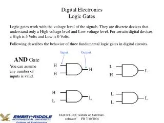
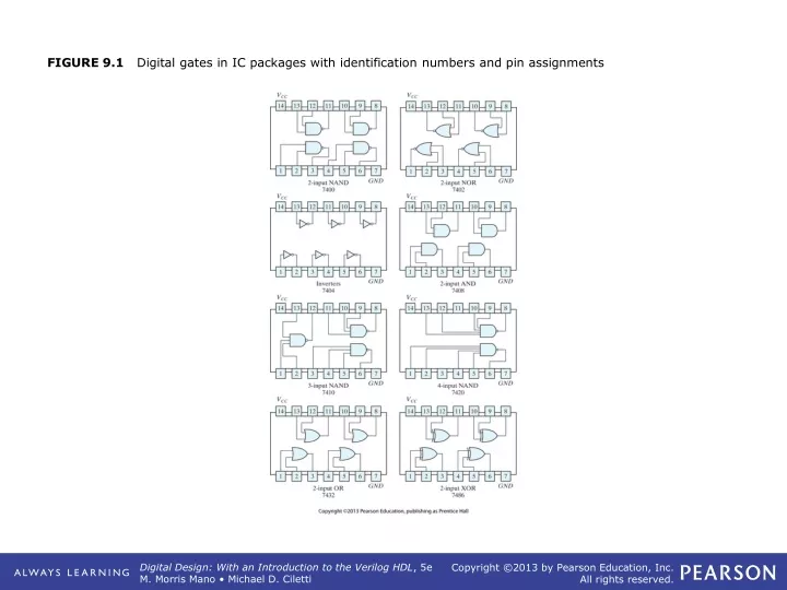
FIGURE 9.1 Digital gates in IC packages with identification numbers and pin assignments
FIGURE 9.8 BCD‐to‐seven‐segment decoder (7447) and seven‐segment display (7730)
FIGURE 9.13 IC type 7474 dual D positive‐edge‐triggered flip‐flops
FIGURE 9.19 IC type 74194 bidirectional shift register with parallel load
FIGURE 9.21 IC type 72555 timer connected as a clock‐pulse generator
FIGURE 9.23 Block diagram of a parallel adder for Experiment 16
FIGURE 9.24 ASMD chart, block diagram of the datapath, control state diagram, and register operations of the binary multiplier circuit
FIGURE 9.24 (continued) ASMD chart, block diagram of the datapath, control state diagram, and register operations of the binary multiplier circuit
FIGURE 9.25 Pulser circuit for FPGA implementation of Experiment 1