Download
1 / 23
280 likes | 810 Views
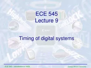
Chapter 11 Timing Issues in Digital Systems. Boonchuay Supmonchai Integrated Design Application Research ( IDAR ) Laboratory August 20, 2004; Revised - July 5, 2005. Goals of This Chapter. Introduction to timing issues in digital design Classification of Digital systems

E N D
Chapter 11Timing Issues in Digital Systems Boonchuay Supmonchai Integrated Design Application Research (IDAR) Laboratory August 20, 2004; Revised - July 5, 2005
Goals of This Chapter • Introduction to timing issues in digital design • Classification of Digital systems • Impact on performance and functionality • Clock Skew • Clock Jitter • Clock-Distribution Techniques Timing Issues in Digital Systems
Timing Classifications • Synchronous systems • All memory elements in the system are simultaneously updated using a globally distributed periodic synchronization signal (i.e., a global clock signal) • Functionality is ensure by strict constraints on the clock signal generation and distribution to minimize • Clock skew (spatial variations in clock edges) • Clock jitter (temporal variations in clock edges) Timing Issues in Digital Systems
Timing Classifications II • Asynchronous systems • Self-timed (controlled) systems • No need for a globally distributed clock, but have asynchronous circuit overheads (handshaking logic, etc.) • Hybrid systems • Mesochronous and Plesiochronous Systems • Synchronization between different clock domains • Interfacing between asynchronous and synchronous domains Timing Issues in Digital Systems
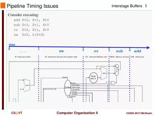
Under ideal conditions (i.e., when tclk1 = tclk2) T tc-q + tplogic+ tsu thold≤ tcdlogic + tcdreg Maximum Clock Period, T R1 R2 Combinational Logic In D D Q Q tclk1 tclk2 clk tplogic, tcdlogic Synchronous System Timing Basics tc-q, tsu, thold, tcdreg tc-q, tsu, thold, tcdreg Timing Issues in Digital Systems
power supply 4 capacitive load 6 clock generation interconnect 3 1 capacitive coupling 7 PLL clock drivers 2 temperature 5 Clock Uncertainties • Under real conditions, clock signal can have both spatial and temporal variations • Systematic (Deterministic) - easy to model and correct for at design time • Random - difficult to model and eliminate Timing Issues in Digital Systems
Clock Nonidealities • Clock skew, tSK (Pink + Orange) • Spatial variation in temporally equivalent clock edges • Can be either deterministic or random or both • Clock jitter (Blue + Orange) • Temporal variations in consecutive edges of the clock signal • Modulation and random additive noise • Short term (cycle-to-cycle) tJSand long term tJL • Variation of the pulse width • Important for level sensitive clocking Timing Issues in Digital Systems
Clk tSK Clk tJS Clock Skew and Jitter • Both clock skew and jitter affect the effective cycle time • Only clock skew affects the race margin Timing Issues in Digital Systems
# of registers Latest occurrenceof Clk edge Nominal + /2 Earliest occurrenceof Clk edge Nominal – /2 Clk delay Insertion delay Max Clk skew Distribution of Clock Skew Negative Positive Timing Issues in Digital Systems
R1 R2 Combinational Logic In D D Q Q tclk1 tclk2 clk delay 1 3 2 4 Positive Clock Skew • Clock and data flow in the same direction T T + >0 + thold T + tc-q + tplogic + tsu so T tc-q + tplogic + tsu - thold + ≤ tcdlogic + tcdregso thold≤ tcdlogic + tcdreg - Timing Issues in Digital Systems
R1 R2 Combinational Logic In D D Q Q tclk1 tclk2 clk delay 1 3 2 4 Negative Clock Skew • Clock and data flow in opposite direction T T + < 0 T + tc-q + tplogic + tsu so T tc-q + tplogic + tsu - thold + ≤ tcdlogic + tcdregso thold≤ tcdlogic + tcdreg - Timing Issues in Digital Systems
R1 Combinational Logic D Q In tclk clk Clock Jitter • Jitter causes T to vary on a cycle-by-cycle basis T +tjitter -tjitter T - 2tjitter tc-q + tplogic + tsu so T tc-q + tplogic + tsu + 2tjitter Jitter directly reduces the performance of a sequential circuit Timing Issues in Digital Systems
R1 R2 Combinational Logic In D D Q Q tclk1 tclk2 T T + 1 > 0 6 12 -tjitter Combined Impact of Skew and Jitter • Constraints on the minimum clock period ( > 0) T tc-q + tplogic + tsu - + 2tjitterthold ≤ tcdlogic + tcdreg – – 2tjitter Timing Issues in Digital Systems
Note on Clock Skew • ForPositive Clock skew: > 0 improves performance, but makes thold harder to meet. If thold is not met (race conditions), the circuit malfunctions independent of the clock period! • For Negative Clock skew: < 0 degrades performance, but thold is easier to meet (eliminating race conditions) • For Skew with Jitter: > 0 with jitter degrades performance, and makes thold even harder to meet. (The acceptable skew is reduced by jitter.) Timing Issues in Digital Systems
Clock Distribution Networks • Clock skew and jitter can ultimately limit the performance of a digital system, so designing a clock network that minimizes both is important • In many high-speed processors, a majority of the dynamic power is dissipated in the clock network. • To reduce dynamic power, the clock network must support clock gating (shutting down (disabling the clock) units) Timing Issues in Digital Systems
Clock Distribution Factors • Things to consider • Interconnect material used for routing clock • Shape of network • Clock drivers and buffers used • Load on clock lines • Rise and fall time of clock (may have to consider transmission line effects as well!!) • Skew specifications Timing Issues in Digital Systems
Clock Distribution Techniques • Balanced paths (H-tree network, matched RC trees) • In the ideal case, can eliminate skew • Could take multiple cycles for the clock signal to propagate to the leaves of the tree • Clock grids • Typically used in the final stage of the clock distribution network • Minimizes absolute delay (not relative delay) Timing Issues in Digital Systems
Idle condition Gated clock Clock H-Tree Clock Network Insert clock gating at multiple levels in clock tree Shut off entire subtree if all gating conditions are satisfied Clock • If the paths are perfectly balanced, clock skew is zero Timing Issues in Digital Systems
DEC Alpha 21164 (EV5) • 300 MHz clock (9.3 million transistors on a 16.5x18.1 mm die in 0.5 micron CMOS technology) • single phase clock • 3.75 nF total clock load • Extensive use of dynamic logic • 20 W (out of 50W) or 40% in clock distribution network • Two level clock distribution • Single 6 stage driver at the center of the chip • Secondary buffers drive the left and right sides of the clock grid in m3 and m4 • Total equivalent driver size of 58 cm !! Timing Issues in Digital Systems
DEC Alpha 21164 Timing Issues in Digital Systems
Clock Skew in Alpha Processor • Absolute skew smaller than 90 ps The critical instruction and execution units all see the clock within 65 ps Timing Issues in Digital Systems
Dealing with Clock Skew and Jitter • To minimize skew, balance clock paths using H-tree or matched-tree clock distribution structures. • If possible, route data and clock in opposite directions • Eliminates races at the cost of performance. • The use of gated clocks to help with dynamic power consumption make jitter worse. • Shield clock wires (route power lines – VDD or GND – next to clock lines) to minimize/eliminate coupling with neighboring signal nets. Timing Issues in Digital Systems
Dealing with Clock Skew and Jitter II • Use dummy fills to reduce skew by reducing variations in interconnect capacitances due to interlayer dielectric thickness variations. • Beware of temperature and supply rail variations and their effects on skew and jitter. Power supply noise fundamentally limits the performance of clock networks. Timing Issues in Digital Systems