Download
1 / 31
310 likes | 453 Views
Wireless LANs and Introduction to IP. Slide Set 7. Wireless LANs. Wireless proliferating rapidly. IEEE 802.11 --> link access standard designed for use in a limited geographic setting. Various versions 802.11a, 802.11e, 802.11g, 802.11n. Physical layer evolution -- increased rates .

E N D
Wireless LANs and Introduction to IP Slide Set 7
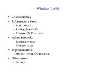
Wireless LANs • Wireless proliferating rapidly. • IEEE 802.11 --> link access standard designed for use in a limited geographic setting. • Various versions 802.11a, 802.11e, 802.11g, 802.11n. • Physical layer evolution -- increased rates . • As an example, 802.11n uses multiple antennas -- can provide very high data rates.
Physical Properties • Typically use 3 kinds of physical media -- two based on spread-spectrum and one based on IR. • IR : limited range. (not much in use) • Spread spectrum -- spread signal over a higher frequency -- provides • reduced impact from external interference. • more robustness to signal loss.
Fading • Signal travels and reflects off objects. • Multiple copies converge at receiver (Red copy and Green copy). • Copies interfere -- may self destruct -- called multipath fading. • Signal combination depends on frequency of transmission.
Spread Spectrum • The use of larger bandwidth provides robustness to fading/interference. Wiped out frequencies
Frequency hopped Spread Spectrum • Transmit signal over a random sequence of frequencies (not really random but pseudo-random). • Computed using a pseudo-random sequence generator. • Receiver uses the same generator -- they can synchronize (same seed).
Direct Sequence Spread Spectrum • Each bit translated into ‘N’ random symbols called chips. • Random chips generated using the pseudo-random number generator. • Transmitted sequence called a n-bit chipping code. • If receiver knows the chips, it can decode. • Others cannot, they see a higher frequency signal -- can be filtered out as noise.
802.11 PHY layers • One PHY layer uses frequency hopping over a 79.1 MHz range. • A second version uses a 11 bit chipping sequence. • Both run in the 2.4 GHz band. • Note: For other than the intended receiver signal looks like noise.
Medium Access Control • Can we use the same protocol as in the Ethernet ? • Carrier Sensing -- Sense channel, transmit when channel is idle, back-off when collision occurs ? • Not really -- why ?
Hidden Terminals • B can talk to A and C but not D. • C can talk to B and D but not A. • A sends to B -- C cannot make out (cannot sense), and it sends to D. • Collision at B :(. • A and C are hidden from each other -- hidden terminal problem.
Exposed Terminals • On the other hand, if B is sending A, C will sense channel to be busy. • Will not send to D. • Not good either! • C is “exposed” to B’s transmission.
The MACA scheme • 802.11 addresses these problems by using an algorithm called MACA -- multiple access with collision avoidance. • Also referred to as “virtual carrier sensing”. • Sender sends a “Request to Send” or RTS to Receiver. • Tells sender’s neighbors of intent to send. • Receiver sends a “Clear to send” or CTS to sender. • Tells receivers neighbors of intent to receive.
Example • A sends to B. • A’s RTS tells everyone in its neighborhood that it is sending. • B’s CTS tells everyone in its neighborhood that it is receiving. • Now C knows that B is receiving and does not initiate communications with D.
Details • RTS indicates the time for which the sender wishes to hold the channel. • Receiver echoes this “duration” field to the sender. • Every node knows -- how long the transmission is for.
Data transfer • Upon a successful RTS/CTS exchange, nodes initiate data transfer. • Receiver sends ACK after successfully receiving frame. • Exposed terminal issue left alone • Random wait when CTS is not received • Back-off similar to what happens with Ethernet.
Access Points • While 802.11 facilitates operations in an “ad hoc” mode, typically, some of the wireless nodes connected to a wireline infrastructure. • These are called access points (APs) -- some people also call them base-stations (more appropriate for cellular networks) • Other mobile hosts connect to the Internet via these APs.
Distribution System • APs connected via the distribution system -- could be Ethernet or FDDI based (or anything else). • Distribution system runs at Layer 2 -- not Layer 3 (Network Layer) entity.
Selection of APs • Via a process called scanning. • When a node wants to select an AP, it sends a probe message. • APs that get this, respond with a Probe-Response. • Node selects one of the APs (strongest signal ?),and sends an Association Request. • Selected AP responds with an Association Response. • Active scanning -- Probes sent actively when mobile joins the network or moves around and out of coverage. • Passive scanning -- APs send beacons -- mobiles hear and if they find a more attractive AP, they can switch.
Rest of Chapter 2 • Read about 802.11 Frame format. • Section 2.9 about Network adaptors and Device Drivers -- self study. • We skip Chapter 3 and move on to Chapter 4.
The Internet • A Network of Networks A Logical interconnection of physical networks.
The Internet Protocol • Architecturally above the Link layer. • Ties together various link layer possibilities.
Service Model • Best effort -- no delivery guarantees. • Fundamental unit is the IP datagram. • Sent in a connectionless manner. • No advance set up. • Datagram contains enough info. to let network forward it to correct destination. • Unreliable.
The IP Datagram • HLen --Header Length • TOS -- Type of Service -- can distinguish connections. • Set priorities. • Length -- Maximum size = 64 KB = 65,535 B • TTL -- time to leave -- discard packets that have been going around in loops. • In terms of hop count (was originally in seconds)
More about the datagram • Protocol -- Binds with transport layer --TCP/UDP. • Checksum -- Consider IP datagram as a sequence of 16 bit words. Add words. Take one’s complement. • Destination/ Source address -- 32 bits for IPv4. • Flags and Offset - used in fragmentation/reassembly
Fragmentation/Reassembly • Each underlying network has a max frame size -- Ethernet 1500 bytes/ FDDI -- 4500 bytes. • MTU -- largest IP unit that the network can carry in a frame. • IP datagram needs to fit into the link layer payload. • If the MTU over a network is smaller, the “router” receiving the datagram will fragment the datagram.
Fragmentation/Reassembly (cont) • All fragments of same datagram contain a unique identifier -- in the Ident field. • Fragments of a datagram are re-assembled at end-host. • If fragments are missing, entire datagram discarded -- TCP/UDP cannot handle fragmented segments.
An Example • Maximum Ethernet size = 1500, Maximum FDDI size = 4500 and maximum PPP size = 532. • IP header -- 20 bytes.
To Note.. • Each IP Datagram is an independent datagram that is transmitted over a series of physical networks. • Each IP datagram is re-encapsulated for every physical network it travels across.
Flag and Offset fields • Flag has a bit called the M bit -- set to indicate that further fragments on their way. • Not set for the final fragment. • Offset -- Indicates offset from original datagram. • In the previous example, offset for first fragment on PPP network = 0. • For the second fragment, offset = 512 and so on. • A detail: Fragmentation to be done in 8 byte units of data -- Offset field counts only in units of 8 bytes. • Assignment: Read code on Reassembly-- Implementation -- Important -- what are maps ? why are holes created ? how can they be filled ?
Next in Chapter 4... • Addressing with IP • Routing. • Achieving scalability -- Global Internet. • Sections -- 4.1 4.2 and 4.3