Download
1 / 30
380 likes | 858 Views
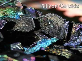
Silicon Carbide. Department of Electronics http://www.ttu.ee/elektron Prof. Dr. Toomas Rang trang@edu.ttu.ee Address Ehitajate tee 5 19086 Tallinn ESTONIA Phone: +372 6 202 150 Fax: +372 6 202 151. Silicon Carbide – trend to top?. Silicon Carbide.

E N D
Silicon Carbide Department of Electronics http://www.ttu.ee/elektron Prof. Dr. Toomas Rang trang@edu.ttu.ee Address Ehitajate tee 5 19086 Tallinn ESTONIA Phone: +372 6 202 150 Fax: +372 6 202 151
Silicon Carbide The crystal growth quality road map In 2005 • 3” wafers available • with 0.2 micropipes/cm2 • less than 50 dislocations/cm2
Silicon Carbide Electronic Energy processing has many parallels with information processing • Both technologies have electromagnetics as a fundamental limit • Both technologies are eventually thermo-mechanically limited (i.e. in terms of interface reliability and loss density) • Both technologies are materials limited • New applications for both are driven by a relentless downward cost spiral
Silicon Carbide 6.5x103 cm2 in hour World Wide is minimum profitable production volume for semiconductor wafers Reality today is • Si 6.5x106 cm2 in hour • SiC 6.5x102 cm2 in hour (military) • SiC 6.5x101 cm2 in hour (others)
Silicon Carbide • Must we nevertheless continue with Silicon?
Silicon Carbide • Figures of merit • KFM – Key’s Figure of Merit (IC Applications) • KFJ – Johnson’s Figure of Merit (High Power Applications)
Silicon Carbide The major demands for metal layers are • Low resistivity for Ohmic, or low leakage currents for Schottky contacts • Easy to form • Easy to etch for pattern generation (e.g. microelectronics approach) • Stable in oxidizing ambient; (e.g. microelectronics approach) • Mechanical stability - good adherence, low stress; • Surface smoothness • Stability throughout processing • Generally no reaction with other metals • Should not contaminate devices, wafers, or working apparatus; • Long lifetimes • Low electromigration
Silicon Carbide Bonding process has the following important advantageous • one-step high temperature process for manufacturing multi-layer contacts (low energy process); • extra high adhesion between layers to be joined; • minimum number of inhomogeneities on large area (near defect free contacts); • improves significantly the certain electrical characteristics of manufactured semiconductor devices compared to other technologies
Silicon Carbide Cline’s initial proposal of two-stage mechanism describes the Diffusion Welding (DW) • The applied load causes plastic deformation of the surface asperities thereby reducing interfacial voids. • Bond development continues by diffusion controlled mechanism including grain boundary diffusion and power law creep Generally the surface should be prepared better than 0.4 m
Silicon Carbide Materials to be bonded • Direct Bonding • Interlayer needed • Not examined
Silicon Carbide Interlayers • Generally these layers are needed to join the incompatible materials, for example aluminum and steel. • Another use of compliant interlayer is to accommodate mismatch strains generated when bonding materials have widely different thermal expansion coefficient. This is important in joining ceramics to metals where a five to ten fold difference in thermal expansion coefficients is not usual. • A reason to reduce bonding temperature and time.
Silicon Carbide • Adhesion test
Silicon Carbide • Cristal Defects (comet tails, micropipes)
Silicon Carbide Screw and Edge Defects at the SiC Si-face surface
Silicon Carbide 4H-SiC wafer upper surface
Silicon Carbide • Structure and examples
Silicon Carbide • U-I characteristics
Silicon Carbide • Forward voltage drop: • (a) n0-n-– 4H-SiC (Nd ~ 1x1015 cm–3) • (b) p0-6H-SiC (Na ~ 5x1015cm–3)
Silicon Carbide SEM Picture (made in Furtwangen)
Bn3 Bn2 Bn4 Bn1 Silicon Carbide Inhomogeneities at the SIC surface
Silicon Carbide Schematic barrier height picture
Silicon Carbide Current distribution at Pt-Au-Pt 6H-SiC interface
Silicon Carbide Temperature distribution in Pt-Au-Pt 6H-SiC interface
Silicon Carbide Schottky interface: J = q(nm - n0)vR n0 = NC exp[-(q Bn/k T)] nm = NC exp[-{q (xm) + q Bn}/k T]
Silicon Carbide • What will come next?