Download
1 / 18
210 likes | 262 Views
Explore the multi-scale and multi-domain complexities of MEMS modeling using Hybrids Systems. Learn about challenges, case studies, modeling techniques, and advancements in this field. Discover a new approach to simulating MEMS actuators involving contact.

E N D
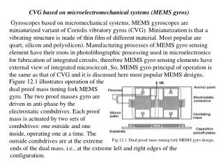
EE291EHybrid Modeling of Microelectromechanical Systems Jason Clark BSAC UC Berkeley
What’s the Motivation Boundary Element Analysis • Currently, there has been great success modeling the electrostatic and structural dynamics of MEMS Finite Element Analysis REF: MEMCAD, Automm Automatic Generation of Dynamic Macromodels
Motivation, cont. Modified Nodal Analysis Mirror Comb-drive array Torsional hinge MEMS modeling is complex due to multi-scales and multi-energy domains such as electro-magnetic, mechanical, thermal, digital/analog electrical, etc.
Motivation, cont. • But a particular class of MEMS, such as actuators involving contact, has remained more of a challenge. Abe Lee : UC Berkeley, PhD dissertation (1992) Roger Hipwell : UC Berkeley, MS thesis (1998) Norman Tien : Cornell, thermal impact actuator (2000) *Richard Yeh : UC Berkeley, PhD dissertation (2001) Easier to make than to simulate in current FEA & MNA frameworks * test case
Progression in MEMS simulation • CT : ODEs • E.g. MEMCAD, SUGAR • CT+DE : Mixed signal systems • E.g. SUGAR • CT+DE+FSM : Hybrid systems • E.g. Ptolemy Next step
Why has CT modeling of impact been impractical for MEMS simulation?
First test case: the Inchworm Motor Operation principles
Non-impacted state K1 K2 K1 K1 K1 M1 M1 Holder Mover F2 F1 M2 F1 = f(v1,v2) FSM - A F2 = f(v3)
Impacted State K2 K2 K1 K1 K1 M1 M1 Holder Mover F2 F1 M2 FSM - B
Hold State K2 K2 K1 K1 K1 M1 M1 Mover Holder F1 F2 M2 FSM - C
Hybrid System CT+DT+FSM v1 v2 v3 ti ti+1 ti+2 ti DT: engage pull hold A B/C CT integration for FSM - A CT integration for FSM – B/C
Q - Switching Gap(X1) < 0.1mm Free Pull Gap(X2) < 0.1mm F2RXN < 1mN & F1RXN < 1mN F2RXN < 1mN Hold Inchworm Loop Gap vs FRXN guards are used to tame Zeno behavior. They widen the marginal thresholds for switching.
Sugar to Ptolemy where G=conductance ce=constitutional eqs C=capacitance c=C contribution V=voltage Q=charge M=mass D=damping K=stiffness F=force q=displacement Electrical & Mechanical = Coupled MNA solution vector MNA matrix Excitation vector Multi-domain state vector Input coupling matrix System matrix 1st order ODE
Hybrid execution • Time propagates to all components • t is global • System is CT at each integration time point • Within DT and a FS • FSM cannot make transitions during t+dt • Time stands still during transitions • After dt FSM examines switching thresholds • At t = t + dt • FSM makes transitions according to guards • Switching control • FSM performs actions on the transition • Initial conditions are set for new state Zeno execution: An execution is Zeno is it contains an infinite number of transitions in a finte amount of time. An automaton is Zeno if it accepts a Zeno execution.
E.g. Sticky Mass K2 K1 M2 M1 FSM-A F1 FSM-B/C