Download
1 / 41
420 likes | 674 Views
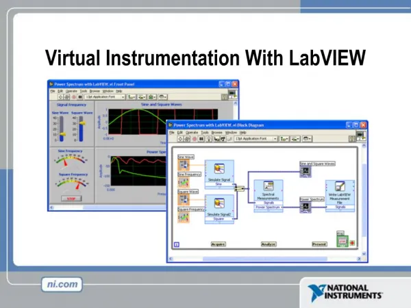
Control & Output with LabVIEW Thursday, Feb 2nd. LabVIEW DAQ Output for Voltage, Sensor Excitation, and Control Systems. Part 1: A Brief History of Some LabVIEW Stuff You’ve Done So Far in ME-241. LabVIEW Application (Review).

E N D
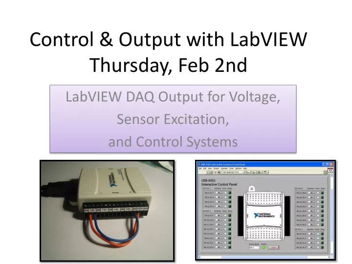
Control & Output with LabVIEWThursday, Feb 2nd LabVIEW DAQ Output for Voltage, Sensor Excitation, and Control Systems
Part 1:A Brief History of Some LabVIEW Stuff You’ve Done So Far in ME-241
LabVIEW Application (Review) • LabVIEW can work with Data Acquisition (DAQ) Platforms in order to capture signals from a variety of instruments. • These include the instruments you have used so far in ME241, such as: Thermocouples, Pressure Transducers, Load cells, Strain gages (& anything that uses a Strain gage) Linear Variable Differential Transformers
LabVIEW Application (Review) • We capture data in the form of electrical signals by wiring our instrument into a DAQ device. • These devices include boards that plug into the PC via a USB-port or… • More sophisticated devices that use PCI cards inside a PC that plug into some benchtop device.
LabVIEW Application (Review) The DAQ devices allow us to capture signals from a given instrument. These instruments allow us to measure the physical phenomenon that we are interested in.
LabVIEW VI Creation In class and laboratory we have used LabVIEW to write virtual instruments (VIs). We typically write a VI so that it can “talk” to the outside world (the experiment on the bench). In order to do this we use the DAQ Assistant.
LabVIEW VI Creation We use the LabVIEW block diagram to create code that measures, displays and records voltages….
The DAQ Assistant is key…. The DAQ Assistant allows us to tell LabVIEW which channels on the DAQ device to sample. For instance if we use a USB-6008 we might set up four channels as follows…
DAQ Device Output Most DAQ devices have the ability to generate signals as well as collect signals. The DAQ devices are able to do this via the port they connect to via a cable. Most standard DAQ devices can generate a signal of 5-10 VDC. This voltage is ample enough to power some small transducers and instruments. This is important to the proper collection of data.
Tank Draining Experiment Apparatus • We use a battery to power the pressure transducer. The battery provides 9 volts. + + + 9 VDC Battery Pack Tank - - - Pressure Transducer Tube
Tank Draining Experiment ApparatusPossible Alternative • We could have used a DAQ Device to power the pressure transducer • Advantage: PC provides power. Batteries not needed. Power provided is “steady.” SCXI to PC AO0 Tank 9 VDC Output From DAQ Device Tube Pressure Transducer
Voltage Output • The BASICS: Most DAQ devices have the ability to produce their own signals. We can use these signals to interact with the experiment or equipment we are using. We can use these signals to power equipment. We can use these signals to trigger events and make stuff happen.
LabVIEW Application MAX • The BASICS: You need 3 things….. DAQ Device
Voltage Output Note the ANALOG side of the USB devices near your computers. There should be terminals labeled AO0 and AO1 AO stands for Analog Output. Most of the NI devices have at least 2 such terminals For output we wire a terminal and a ground.
Voltage Output • We access the analog output functions via LabVIEW. To do this we can access the DAQ Assistant. • We can right-mouse click and access Functions on the Block Diagram. • Select the DAQ Assistant on the OUTPUT Menu
Voltage Output • When the DAQ Assistant is selected you get 2 choices: • “Acquire Signals”…what we have used so far • “Generate Signals” choose this one for voltage output!
Once you select Generate Signals choose Voltage • The device or devices will appear. Choose either one or both channels (depending on how many signals must be generated.)
DAQ Assistant for Voltage Output Compare Differences/Similarities
Build a Control to Dial 0-5 volts On the Front Panel place a dial. Connect this to “data’ on the Output DAQ Assistant.
Build a Control to Dial 0-5 volts Turn the knob to some arbitrary value and press the run arrow. This vi will produce…
We can confirm this value by adding an INPUT DAQ Assistant. Build one that reads from input channel AI1. Add a graph or indicator to your vi to show output.
Exercise: Build A VI to Generate an Output and Collect that Voltage as an Input
Part 4: Applications and Demonstrations
DEMO Application 1 • Sometimes we need more than just 5 or 10 volts • How can the LabVIEW output function help us to run a pump or motor? Application: We need to use LabVIEW to control a motor. The motor uses a variable voltage from 60 to 120 volts to adjust from top speed to low speed.
DEMO Application 1 In this case we would use a device with the motor’s manual control electronics. The controller will accept a grounded DC signal and generates a proportional output voltage. This output can be supplied to the speed setting circuit of the motor’s controller. This will drive the motor at a speed proportional to the signal that LabVIEW sends to it.
DEMO Application 1 Turn-Table with experiment Main power supplied By 120 VAC outlet 0-10 VDC “control” volts from LabVIEW Control box With SCR-based potentiometers Power line from control Drive Motor
DEMO Application 2 Using LabVIEW with advanced NI hardware. In this example we want to send simple commands to control the speed of a stepper motor. We will use a PCI-card in the PC, a “smart” encoder/motor power board, and LabVIEW software.
Demo Application 2 stepper Coil wires LabVIEW Control VI SCXI cable PCI-card
Demo Application 3 • Use LabVIEW to send commands and receive data from a balance. • In this case we have no DAQ or PCI cards • We can only use the PC’s serial port to “talk” to the balance.
Demo App 3: Balance vi • To use a “stand-alone” instrument like the balance we have to: • 1. write a vi that talks to a serial port • 2. wire up a cable per the manufacturer’s specs The vi reads… 0.847 g PC 0.847 g Cable has 2 RS-232 (9 pin) connectors Balance
Demo Application 3 • In this case we will “write” data to the balance using LabVIEW. • LabVIEW will assign the serial port to transmit data (Tx) and commands to the balance. • The balance will use the same port to send (Rx) data and information. • In this case we will use a vi called a binary converter in order to write between LabVIEW and the balance.
DEMO Application 4 • Using LabVIEW with non-NI hardware. • In this example rather than control voltage directly via a DAQ we will send commands directly to circuit boards. • As in the Balance DEMO we will use only the serial bus to link LabVIEW with the circuit boards. • HOW can LabVIEW talk directly to a circuit board?
DEMO Application 4 • We talk to the circuit board by using “Op-Code.” • Op-Code will serve as a bridge between LabVIEW and the binary assembly language that a circuit board expects to see.
DEMO Application 4 Think of it as translation… English SpanishIrish “Good Morning” “Buenos Dias” “Diaduit!” LabVIEWPC InterfaceCircuit Board “G-Code” “Op-Code”“Assembly”
DEMO Application 4 PC with LabVIEW Serial Communications Card Power Supply 24 VDC 0-15 volts Power Board with SCR-based Transformer Train Track