Download
1 / 18
180 likes | 360 Views
PHOTOVOLTAIC CELLS BASED ON ORGANIC THIN LAYERS. Stefan ANTOHE Faculty of Physics, University of Bucharest, P.O.Box MG-11, Bucharest-Magurele, 077125 ROMANIA E-mail:santohe@solid.fizica.unibuc.ro. Seminar National de “Nanostiinta si nanotehnologie”,

E N D
PHOTOVOLTAIC CELLS BASED ON ORGANIC THIN LAYERS Stefan ANTOHE Faculty of Physics, University of Bucharest, P.O.Box MG-11, Bucharest-Magurele, 077125 ROMANIA E-mail:santohe@solid.fizica.unibuc.ro Seminar National de “Nanostiinta si nanotehnologie”, 27 ianuarie 2004, Academia Romana, Bucuresti
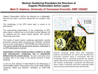
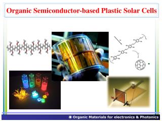
Main topics • In this work are summarized the electrical and photoelectrical properties of the organic photovoltaic cells based on the organic thin layers. • The single-layer photovoltaic structures, ITO/CuPc/Al and ITO/TPyP/Al has been prepared and characterised, where the organic layers of CuPc and TPyP, are Copper Phthalocyanine and 5,10,15,20-Tetra (4-Pyrydil)21H,23H-Porphine, respectively. • The photovoltaic structures based on the p-n heterojunction present at the interface between two organic layers, like, ITO/CuPc/TPyP/Al and ITO/Chl a/TPyP/Al, exhibits stronger spectral sensitivity and better spectral matching to a solar spectrum than Schottky cells using either CuPc or TPyP, layer. • Three-layered organic solar cells with an interlayer of codeposited dyes of p-type CuPc and n-type TPyP, between the respective dye layers were also prepared and characterized. They showed increased power conversion efficiency, due to the efficient carrier photogeneration in the enlarged photoactive region from the codeposited layer. • The spectral sensitization of an a-Si:H solar cell using an organic layer was also obtained. The action spectrum was extended by 30 nm to longer wavelength range, using a 100 nm thick layer of TPyP. An exciton dissociation process explains the sensitization of the TPyP/a-Si:H interface, which gives rise of higher quantum efficiency at longer wavelengths.
THE PARAMETERS OBTAINED FOR DIFFERENT ORGANIC SOLAR CELLS The scored progresses in the understanding of photovoltaic mechanism and the development of organic solar cells technologies determined the increase of power conversion efficiency.
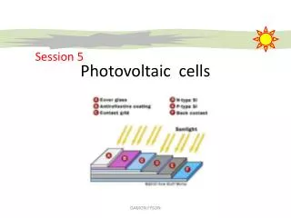
Sample Preparation and Experimental Procedures. • The indium tin oxide (ITO) - the transparent conducting substrate • The organic layers of CuPc, TPyP, on different thickness, were deposited by conventional thermal vacuum evaporation. • The source temperature: 380C for CuPc and 280C for TPyP. • In the case of single-layer cells, a semitransparent top electrode was deposited on the organic layer. • In the case of two-layer cells, the organic layer having p-type conductivity, was firstly deposited on ITO, and then over it the organic layer with n-type conductivity was deposited. • The deposition of the mixed interlayer, in the case of three-layer cells, was carried out by the coevaporation of CuPc and TPyP from two separated sources, on the first deposited CuPc layer. A third layer of TPyP was deposited on top of the codeposited layer. • The current-voltage (I-U) characteristics in the dark and light were measured using a voltage stabilised power source, a Philips microammeter and a Keithley 614 electrometer. • The optical setup: 650 W halogen lamp, monochromator (spectral range of 300 to 900 nm), Perkin Elmer UV-VIS spectrophotometer (Lambda 2S). CuPc (Eastman Kodak Company) TPyP (Aldrich-Chemie Company)
The mono-layer cellsITO/CuPc/Al • Action spectrum of short - circuit photocurrent and absorption spectrum of the organic layers for the Schottky cells ITO/CuPc/Al. • The typical cell parameters at illumination through ITO electrode with monochromatic light ( = 620 nm and ~105 photons/cm2s): • Uoc = 0.675 V, Isc = 8 nA, ff = 0.35, = 0.6x10⁻²%. • Antohe S., et. al. • Rev. Roum. Phys., 34(6) (1989) 665-671. • The dark current - voltage characteristic of ITO/CuPc/Al cell at room temperature. • Transport parameters: • p0 = 2.3x1013 cm-3, = 1.1x10⁻² cm2/Vs, • = 4x10⁻⁸-1cm-1, the equilibrium Fermi level 0.455 eV above the valence band.
The mono-layer cellsITO/TPyP/Al • Transport parameters: • Ohmic region • n0 = 3x109 cm-3; • EF0 = 0.66 eV below (CB); • = 6x10⁻⁴ cm2/Vs; • 0 = 3x10-13-1cm-1 • SCLC region: • Nt = 1.7 x1014 cm-3, • Ec-Et = 0.75 eV ; The dark current - voltage characteristic of ITO/TPyP/Al cell. • Action spectra and absorption spectrum of the ITO/TPyP/Al cell. • The typical cell parameters at illumination through ITO electrode with monochromatic light of 32 W/cm2 at • = 440 nm: Uoc = 0.175 V; Jsc = 42 nA/cm2; ff = 0.13; = 0.27x10⁻²%. Antohe S. Phys. Stat. Sol. (a), 136 (1993) 401-410. • Schematic representation of energy bands at the ITO/TPyP • (50 nm)/Al junction. • = 0.68 eV the barrier height at ITO/TPyP interface; wide of barrierw[193, 50] nm, when the temperature increases from 295 to 360 K;
. Two-Layer Organic Photovoltaic Cells:ITO/CuPc/TPyP/Al The dark current-voltage charac-teristic of ITO/CuPc /TPyP/Al • Action spectrum of: (a) ITO/CuPc/Al; • (b)ITO/TPyP/Al, and the absorption • spectrum of the organic layer. • Jph 600 nm = 37.2 nA/cm2; ff=0.12; • = 0.6x10⁻²%. • b) Jph440 nm = 28.8 nA/cm2; ff=0.13; • = 0.27x10⁻²%. • Antohe S. and Tugulea L., • Phys. Stat. Sol. (a) 128 (1991) 253-260. • Action spectra of ITO/CuPc/TPyP/Alcell. Curves obtained at illumination of the Al and ITO electrodes, respectively. (1) Jph400 nm = 0.845 nA/cm2, (2) Jph600 nm = 223 nA/cm2. • b) Optical absorption spectrum of the CuPc/TPyP two layer film Jph-V characteristic in PV mode.The typical cell parameters at illumination through ITO with 20 W/cm2 at 440 nm: Uoc = 0.4 V; Jsc = 135 nA/cm2; ff = 0.44; = 0.12%.
Two-Layer Organic Photovoltaic Cells:ITO/Chl a /TPyP/Al a) Absorption spectrum of Chl a/TPyP films (a), Chl a layer (b), and TPyP layer (c). b) Action spectra of cells illuminated through ITO: ITO/Chl a/Al (1), ITO/Chl a/Al (2), and ITO/TPyP/Al (3). S. Antohe, et. al. Phys. Stat. Sol. (a) 153, 581 (1996) The dark I - V characteristic of ITO/Chla(200 nm) / TPyP (100nm) /Al cell in the dark Current - voltage charac teristic for the ITO/Chl a/TPyP/Al cell in the fourth quadrant, under illumination with mono-chromatic light of 20 W/cm2 at 470 nm. • The typical photovoltaic cell parameters under monochromatic light of 20 W/cm2 at 470 nm: • Uoc = 490 mV; Jsc = 13 nAcm-2; ff = 0.34; =1.1x10⁻²%,.The ff=0.34 is beter than the values of 0.09 and 0.13 for ITO/Chla/Al and ITO/TPyP/Al Schottky cells, respectively. • The isabout 2-3 times higher than for ITO/Chla/Al cell.
Three - Layered Photovoltaic CellITO/CuPC/(CuPc+TPyP)/TPyP/Al where =q/nkT, (2) • For higher forward bias, where Rs affects the curves, Eq. (1) can be writen as I=I0exp[(U-IRs)], and since 1/Rsh < I, Eq.(2) becomes R0 =Rs+1/I (3) • For low voltages, where Rsh acts, I0exp[(U-IRs)]<< 1/Rsh and then, Eq.(2) becomes: R0 = Rs+Rsh(4) The dark current-voltage characteristics of the ITO/CuPc/(CuPc+TPyP)/ TPyP/Al cell. • From the extrapolated linear region [A], the value of Rs is 5.82 M, and Rsh, obtained from region [B] is ~ 2 G. • To improve the linearity of ln(I)-U plot, for determination of n and I0, we firstly removed the effect of Rs. This was achieved by making the change in variable of Y = U-IRs(5) • With this change, Eq. (1) becomes:I = I0[exp(Y)-1]+Y/Rsh (6) • For high forward biases, Eq.(6) becomes: I=I0exp(Y) (7) • Plotting ln(I-Y/Rsh) vs. Y, we remove the effect of Rsh. • The removal of Rsh and Rs has lead to the increase in the linearity of the curve at lower biases from 0.3V to 0.1V and at higher biases from 0.7 to 0.8 V, respectively. • The whole linear region of ln(I)-U plot is extended in the range 0.1-0.8V. • n and I0 are 2.79 and 6.2x10⁻¹³A, respectively and are more reliable than those obtained after the removal of Rs only. • For biases > 0.8V, the current follows the relation I ~ Um where m = 7. This suggests that the dark current is a (SCLC) in the presence of exponentially distributed traps. • JSCLC = Neffq1- [/Nt(+1)] [(2+1)/(+1)]+1 (U +1/d 2+1) (8) • where = Tc/T, where Tc is a “characteristic temperature”. [A] Semilogarithmic plots of the forward-biased current: I-Y/Rsh vs Y. [B] Logarithmic plot of I-V SCLC for high forward biases The junction resistance R0 as a function of 1/I. The insert is the region A of high currents
Three - Layered Photovoltaic CellITO/CuPC/(CuPc+TPyP)/TPyP/Al The action spectra of the cells: [A] ITO/CuPc/(CuPc+TPyP)/TPyP/Al [B] ITO/CuPc/TPyP/Al, illuminated through ITO electrode The absorption spectra of (a) TPyP and b) CuPc layers • Although the absorption spectra of TPyP and CuPc layers, are nearly complementary (the main maxima of TPyP and CuPc layers are centred at 430 and 620 nm, respectively), both the TPyP and CuPc layers contribute to the photogeneration of carriers in the cells. • It is important to note that, although both TPyP and CuPc layers show a moderate absorption at wavelength of 520nm, a peak of photocurrent exists at this wavelength. • This behaviour shows strongly that the photoactive region there is at theCuPc/TPyP interface
Three - Layered Photovoltaic CellITO/CuPC/(CuPc+TPyP)/TPyP/Al The parameters: Uoc, Jsc, ff , , have been determined from the right figure. a) The fill factor has different values ranging from 0.11 to 0.32. These low values are due to two separate effects: the high series resistances and the field-dependent nature of the photogeneration of charge carriers [2, 8]. b) The better performance of the cell are obtained for more penetrating 520 nm wavelength and 30 W/cm2 input powers. These values are about 2-3 times larger than those of a two-layer cell and are among the best reported for organic solar cells. The better performance of the cell at shorter wavelength is most probable due to the bulk ionisation of more energetic 520 nm excitons into charge carriers, mainly in TPyP layer.S. Antohe, et. al. J. Phys. III France 6 (1996) 1133-1144 Jph – U characteristics of the ITO/CuPc/ (CuPc+TPyP)/TPyP/Al cell illuminated with: [A] 520 nm wavelength, for: (3 W/cm2 [a], 12 W/cm2 [b] and 30 W/cm2 [c]); [B] 590 nm wavelength, for: (6 W/cm2 [a], 30 W/cm2 [b] and 72 W/cm2 [c]).
The photosensitized ITO/a-Si:H p-i-n/TPyP/Au cells Cell configuration (inset) and current-voltage characteristics of ITO/a-Si:H p-i-n/TPyP/Au cell The rectification ratio (Rr = 104 at 0.6 V). The parameters n and I0, have the values: 2.6 and 1.14x10⁻¹⁰A, respectively The ITO/a-Si:H p-i-/TPyP/Au cell behaves as p-i-n junction combined with high Rs S. Antohe, et. al. Solar Energy Materials&Solar Cells 62, 207-216 (2000) . The action spectra of short-circuit photocurrent of: (a) ITO/a-Si:H p-i-n/Au and (b ITO/a-Si:H p-i-n /TPyP/Au cells. (c) Optical absorption spectrum of TPyP layer The presence of the TPyP film gives rise to a shift of the long-wavelength edge of the action spectrum of approximately 30 nm. The main absorption peaks from 430 nm, 520 nm, 620 nm, of TPyP are reflected in the action spectrum of the sensitized cell. The area of curve (b) is larger than that of curve (a).
Conclusions • 1) The single - layer ITO/CuPc/Al and ITO/TPyP/Al cells have a photovoltaic response as a result of the charge carrier photogeneration in CuPc or TPyP layer and their separation in the built electric field present at Al/CuPc and ITO/TPyP interface, respectively. The values of the typical cell parameters (Uoc, Isc, ff, and ) are in good agreement with those of other organic monolayer cells. 2) The two-layer ITO/CuPc/TPyP/Al cells have a power conversion efficiency of about 100 times greater than that of organic monolayer cells, due to a strong cosensitization effect. The ITO/Chla/TPyP/Al cells show rectification and photovoltaic response due to barrier formed at the Chla/TPyP interface. Various photovoltaic features of ITO/Chla/TPyP/Al cells suggest an improvement, although modest, over ITO/Chla/Al cells. 3) The three-layered organic photovoltaic cells (ITO/CuPc/(CuPc +TPyP)/TPyP/Al), clearly suggest an improvement, over two-layered cells. The codeposited interlayer, has been found to act as an efficient carrier photogeneration layer because: on the one hand, the built-in potential drops across it and on the other hand, here there is the region of maximum photogeneration rate, as a result of exciton dissociation via the exciplex of (CuPc- ....TPyP+ )* dyes. The fill factors of 0.11-0.32 represent an improvement over single and double-layered cells. Moreover, the power conversion efficiencies of three-layered cells, ranging from 0.07 to 0.35%, are 2-3 times greater as compared to those for double-layered cells. 4)The spectral sensitization of an a-Si:H solar cell using an organic layer was obtained. The action spectrum was extended by 30 nm to longer wavelengths range, using a 100 nm thick layer of TPyP. The sensitization is explained by an exciton dissociation process to the TPyP/a-Si:H interface, which gives rise of higher quantum efficiency at longer wavelengths.
[1] Ghosh Amal K. and Feng Tom, J. Appl. Phys. 49, (1978) 5982-5989. [2] Chamberlain G. A., Solar Cells, 8 (1983) 47-83. [3] Fu-Ren Fan and Larry R. Faulkner, J. Chem. Phys., 69 (1978) 3334-3339. [4] Yamashita K., Matsumura Y., Harima Y., Miura S. and Suzuki H., Chem. Letters, 4 (1984) 489-492. [5] Antohe S. and Tugulea L., Phys. Stat. Sol. (a) 128 (1991) 253-260. [6] Antohe S., Rev. Roum. Phys., 37(3) (1992) 309. [7] Kampas F.J. and Gouterman M., J. Phys. Chem., 81 (1977) 690-695. [8] Nevin W.A. and Chamberlain G.A., J. Appl. Phys., 69 (1991) 4324-4331. [9] Antohe S., Phys. Stat. Sol. (a), 136 (1993) 401-410. [10] Harima Y., Yamashita K. and Suzuki H., Appl. Phys. Lett., 45 (1984) 1144-1145. [11] Tang C. W., Appl. Phys. Lett., 48(2) (1986) 183-185 [12] Hiramoto M., Fujiwara H. and Yokoyama M., Appl. Phys. Lett., 58(10) (1991) 1062-1064. [13] Antohe S., Munteanu I., Dima I.,Rev. Roum. Phys., 34(6) (1989) 665-671. [14] Oueriagli A., Kassi H., Hotchandani S. and Leblanc R. M., J. Appl. Phys., 77(11) (1992) 5523-5530. [15] Mark P. and Helfrich W., J. Appl. Phys., 33 (1962) 205-215. [16] Meier H., Organic Semiconductors, (Verlag Chemie, Weinheim 1974). [17] A.K. Ghosh, D.L. Morel, R.F. Show and C.A. Rowe Jr., J.Appl.Phys., 45, 230, (1974) [18] C.W. Tang and A.C. Albrecht, J.Chem.Phys., 63, 953, (1975) [19] F.R. Fau and L.R. Faulkner, J.Chem.Phys., 67, 3341, (1978) [20] G.A. Chamberlain and R.E. Malpas, Faraday.Discuss.Chem.Soc., 70, 229, (1980) [21] G.A. Chamberlain, P.J. Cooneyand, S. Denison, Nature, 289, 45, (1981) [22] A.M. Hor and R. Loutfy, Thin Solids Films, 106, 291, (1983) [23] S. Antohe, I. Munteanu, I. Dima, N. Tomozeiu, V. Mitache, Lucrarile CAS'89, Ed. a-12-a, 65-67, (1989) [24] S. Antohe, L. Tugulea, V. Gheorghe, V. Ruxandra, I. Cåplånus and L. Ion,Phys. Stat. Sol. (a) 153, 581 (1996) [25] S. Antohe, V. Ruxandra. L. Tugulea, V. Gheorghe and D. Ionascu, J. Phys. III France 6 (1996) 1133-1144 [26] L. Tugulea andS. Antohe, Photosynthesis Research II, 845- 849, (1993) [27] S. Antohe, I. Dima, I. Munteanu, Lucrarile CAS'87, Ed. a-10-a, 63-67, (1987) [28] S. Antohe, L. Ion, N. Tomozeiu, T. Stoica, E. Barna, Solar Energy Materials&Solar Cells 62, 207-216 (2000) References